Troubleshooting Camera Link
Overview
Contents
- The Frame Grabber Does Not Appear in NI-MAX
- The Frame Grabber Shows in NI-MAX as "//PCIxxx"
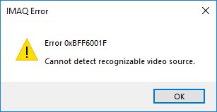
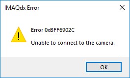
- Unable to Connect to Camera Error 0xBFF6902C or Cannot Detect Recognizable Video Source 0xBFF6001F
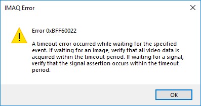
- Timeout Error 0xBFF6901B or 0xBFF60022 or corrupted image
- Additional Resources
The Frame Grabber Does Not Appear in NI-MAX
When first inserting a Camera Link frame grabber in your computer and connecting the camera, NI-MAX can be used to configure and test the camera. The frame grabber should appear under My System >> Devices and Interfaces. If it does not appear at this location, check for the following possible causes:
Case 1: The NI-IMAQdx or NI-IMAQ driver is not installed.
The NI-IMAQdx or NI-IMAQ driver must be installed for a Camera Link frame grabber to be detected.
- In the MAX Configuration window, select My System»Software.
- Expand Software, and verify that NI-IMAQdx or NI-IMAQ appears in the list. If it is not listed, then NI-IMAQdx or NI-IMAQ must be installed. Camera Link support was added in NI-IMAQdx 18.0. If you have a version of NI-IMAQdx older than 18.0, you must have the NI-IMAQ driver installed in order to detect your frame grabber.
- The latest version of Vision Acquisition Software, which includes NI-IMAQdx and NI-IMAQ, can be downloaded from the Software and Drivers Downloads page. You can install it from the NI Package Manager.
Note: NI-IMAQdx is not available for free. You can use it as a full featured evaluation version for 30 days after which you will need to activate for further use. For more information about licensing, refer to Licensing NI Vision Software.
Case 2: The frame grabber is not recognized by the operating system
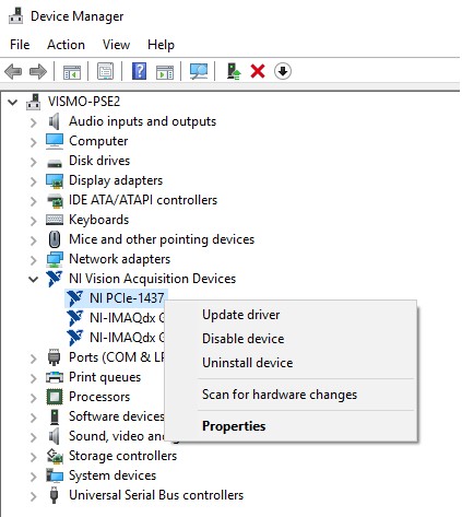
- Open Device Manager
- Expand NI Vision Acquisition Devices
- If you cannot find the frame grabber, this means the operating system was not able to detect it correctly.
- Try another PCIe slot in your computer or reseat the card.
To learn more about the installation of your specific card, refer to its Getting Started Guide.
The Frame Grabber Shows in NI-MAX as "//PCIxxx"
If the board shows up as an unknown resource, this means the driver has not been associated with the card correctly.
- Close NI-MAX
- Open Device Manager
- Expand NI Vision Acquisition Devices
- Right Click on your board and select Disable Device.
- Re-enable the device. Right click on Enable Device.
Unable to Connect to Camera Error 0xBFF6902C or Cannot Detect Recognizable Video Source 0xBFF6001F
If MAX returns error 0xBFF6902C with IMAQdx or 0xBFF6001F with IMAQ, this means that the frame grabber was not able to detect a valid pixel clock coming from the camera. Check for the possible causes:
Case 1: Inadequate power is being provided to the camera
Camera Link cameras can either be powered with Power over Camera Link (PoCL) coming from the Frame Grabber or they can be externally powered. In order to know if your camera supports PoCL, verify the datasheet or manual of your camera model. If it does not support PoCL, you will need to power your camera with an external power supply. If your camera does support PoCL, make sure of the following things:
- PoCL is enabled on the frame grabber. Refer to How do I Enable Power over Camera Link (PoCL) on My Frame Grabber? for more information.
- Cables are PoCL compliant
- If your camera requires power over both connectors, consult the frame grabber's specifications to make sure it supports dual PoCL.
Case 2: Base and Medium/Full Connectors are not connected to their respective connectors on the camera and Frame Grabber
Make sure that the Base Connector (Connector 0) of the Frame Grabber is connected to the Base Connector of your camera and that the Medium/Full Connector (Connector 1) is connected to the respective connector on the camera. Our Frame Grabber is expecting a valid pixel clock signal from the camera on the Base connector, therefore if the Base and Medium/Full connections are swapped, the camera will not be detected correctly.
Timeout Error 0xBFF6901B or 0xBFF60022 or corrupted image
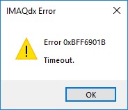
If MAX returns error 0xBFF6901B with IMAQdx or 0xBFF60022 with IMAQ, this means that the frame grabber was not able to acquire a full frame within the specified acquisition timeout time.
Case 1: The image size expected by the frame grabber is bigger than the image sent by the camera
If the image sent by the camera is smaller than the size of the image specified in the camera file, you will get a timeout error since our frame grabber will be expecting more LVAL and FVAL signals from the camera.
In order to verify the size of the image sent by the camera you can use the camera vendor’s software utility.
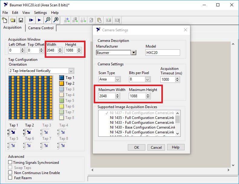
Use the Camera File Generator to modify the Max Image Size and Acquisition Window in the camera file to match your camera’s settings:
Make sure that the Maximum Width and Height in the camera file matches the Maximum resolution of your camera.
As a tip to verify whether the frame grabber is receiving any data from the camera, start with a small acquisition window and a max image size that is a multiple of the camera’s number of taps and 8 (for optimized bus performance). For example, you could set the max width and height to 80 if you have a 10 tap camera or 32x32 for 4 tap or less. Once that works, increase the size of the acquisition to see where it fails.
For more information about creating camera files with the Camera File Generator, refer to Creating a Camera File Using the NI Camera File Generator.
If you cannot use the camera vendor’s utility software to verify your camera’s attributes, you can use the RS-232 port on the NI Frame Grabber to send serial commands to the camera in order to read/write attributes. Refer to Communicating with Serial Port on a Camera Link Camera for more information on how to do that.
Case 2: Tap Configuration and bit depth of the camera does not match the tap geometry and bit depth specified in the Frame Grabber’s camera file
If the frame grabber is expecting a certain tap geometry specified in the camera file but the camera is sending the data bits in a different tap, the expected LVAL and DVAL signals received will not be interpreted correctly. The same issue would happen if the bit depth of the camera does not match the bit depth expected by the frame grabber.
In order to verify whether the tap geometry and bit depth of the camera matches the one specified in the camera file, you can use the camera vendor’s software utility (if available) to look at the camera’s attributes.
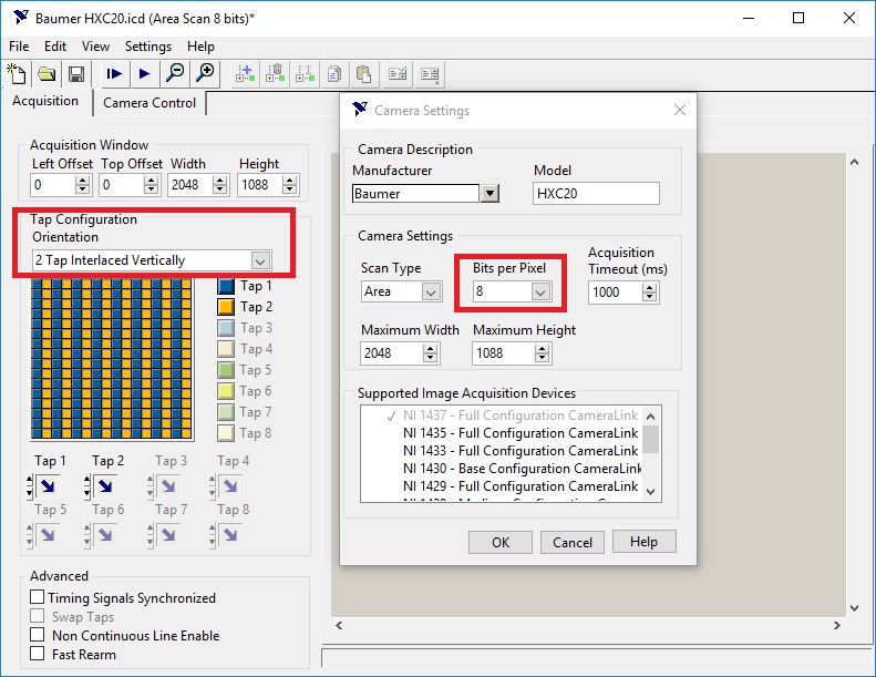
Use the Camera File Generator to modify or verify the tap geometry and bit depth in the camera file to match your camera’s settings:
For more information about modifying or creating camera files with the Camera File Generator refer to Creating a Camera File Using the NI Camera File Generator.
If you cannot use the camera vendor’s utility software to verify your camera’s attributes, you can use the RS-232 port on the NI Frame Grabber to send serial commands to the camera in order to read/write attributes. Refer to Communicating with Serial Port on a Camera Link Camera for more information on how to do that.
Case 3: Camera outputs an inverted or no DVAL signal
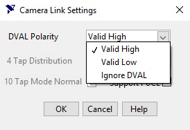
Some Camera Link cameras do not output a DVAL signal but by default our frame grabber looks for that signal in order to acquire the image correctly. If your camera does not use the DVAL signal, make sure to specify this in the camera file. Using the Camera File Generator, go to Settings > Camera Link Settings:
You can choose to either Ignore DVAL or Invert it depending on what the camera outputs.
To verify whether your camera outputs a DVAL signal you can also use the Camera Link Logger in order to record the FVAL, LVAL, DVAL and pixel clock signals coming from the camera.
Using the Camera Analyzer you can also read back those signals for further analysis.
Case 4: Camera or frame grabber trigger is enabled
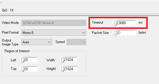
If either your camera or frame grabber is expecting a trigger and does not receive a trigger in the specified timeout time, the acquisition will return a timeout error.
You can increase the timeout in the Acquisition Attributes tab to meet your trigger specifications:
You should also make sure that signals are routed correctly to either your frame grabber or camera.
Case 5: Buffer Overflow on the Frame Grabber
When an acquisition is in progress, the frame grabber continually acquires data from the camera and stores it in memory on the board. At the same time, it continually negotiates with the PCI Express bus for permission to send this data to the computer’s main memory in a First-In-First-Out (FIFO) fashion. If the PCI Express bus is unable to accept data at a rate at least as fast as the incoming rate from the camera, the onboard memory will eventually fill up and the FIFO overflow error is generated: -1074397140 IMG_ERR_FIFO_OVERFLOW.
If this happens, try the following things:
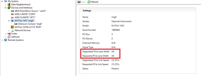
- Verify that the negotiated PCIe lane width is the same as the requested one. This will ensure that the maximum PCIe bandwidth is being used.
If you are not getting the negotiated PCIe lane width, try changing the card to another PCIe slot that has the same number of lanes as the frame grabber you are using.
- If you are using multiple PCIe cards at the same time, PCIe resource contention could happen. Try reducing the traffic over the PCIe bus by reducing the number of cards used.
- Refer to FIFO Error -1074397140 During PCIe-1429 Grab for more information.
To know if you can sustain your acquisition rate without getting a buffer overflow error, refer to How Do I Calculate the Bandwidth Required for My Image Acquisition?
Frame grabbers that support full Camera Link speeds should not encounter this problem. Refer to the first table of Frame Grabber Specifications for the NI Camera File Generator to verify which boards supports up to 80bits of data width.
Case 6: Signal Integrity issues with Camera Link cables
Low quality and/or very long cables can result in signal integrity issues that disrupt the acquisition. Try with shorter or known high quality cables to rule out potential signal integrity issues.
Additional Resources
- Acquiring from GigE Vision Cameras with Vision Acquisition Software
- How to Acquire from GigE Vision Cameras with Vision Acquisition Software
- List of GigE Vision cameras on NI Camera Advisor
- GigE Vision Camera Not Discovered in NI MAX
- Camera Link Getting Started Guide
- Creating a Camera File using the NI Camera File Generator
- Camera Link Tap Geometry Explained
