Camera Link Logger for the NI-1433
Overview
Contents
What Software and Hardware Do I Need?
- NI-IMAQ 4.7
- LabVIEW 2012
- NI-1433
- Camera Link Camera
What Can It Log?
The Camera Link interface is extremely powerful for doing Vision applications, but typically there is no way (short of scoping the lines directly) of finding out what sorts of signals are passing through your frame grabber. This application was constructed to allow customers some access to this information. The data is logged from the NI-1433 and stored in a file which can be read out using the Camera Link Analyzer. The following lines are provided for debugging purpose:
- Frame Valid
- Line Valid
- Data Valid
- Camera Control Line 1
- TTL0
- RTSI0
- Serial In
- Serial Out
These signals can be analyzed, interpreted and viewed in a compressed and decompressed form in the Camera Link Analyzer.
How Do I Use It?
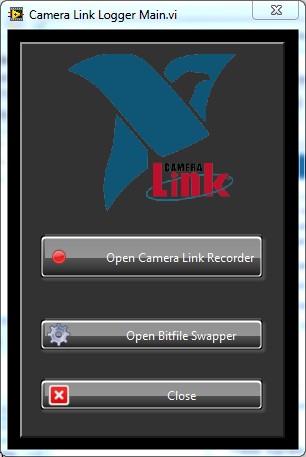
The home screen of the NI-1433 Camera Link Logger Utility is extremely simple. It has links to two interfaces which can be used to perform the logging.
Step 1: Swap Your Bitfiles
In order to log successfully, first close all applications which may access the frame grabber or camera.
Next, open the logger and click Open Bitfile Swapper.
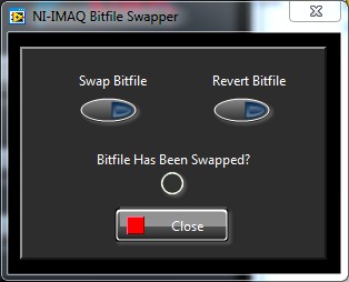
You will see a screen like the following:
You will want to swap the bitfiles for the debugger version. The original configuration of the frame grabber does not allow for these reroutes of signals, but the new file provides them as an interface. Click Swap Bitfile and allow a moment for the configuration to change. Note than you should always Revert Bitfile when you are done logging.
You should see the "Bitfile Has Been Swapped?" LED turn green.
You can now click the Close button to return to the previous screen.
Step 2: Using the Recorder
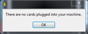
Next, you'll want to click the Open Camera Link Recorder button. If you do not have a frame grabber connected to your computer, you will receive a message like the following:
Assuming you do have cards plugged in, you will see a populated list of serial numbers. You may then select the card with the appropriate serial number that you would like to test. Click Select Current Serial Number when you have selected the serial number you wish to log.
Step 3: Grab or Snap in MAX
The logger will immediately begin watching for a trigger. The trigger is the Start trigger for the camera. At this point you will want to open Measurement and Automation Explorer and click either Snap or Grab (occassionally you may be required to press the button more than one time). You should see the counter in the logger interface begin incrementing. If you have a timeout, you may see the counter freeze temporarily. If the lag time is too long, the logger will stop acquiring, otherwise it will continue in the background and start displaying the increment again once the lag has subsided. Once you have acquired an acceptable amount of samples (10 seconds is more than enough in most cases), click the Stop button.
Step 4: Save and Analyze
You will now be prompted with a dialog box in which you can select the name of the log file. Make sure you recall where you save it.
You may now load that log file using the Camera Link Analyzer and view your signals!
Bonus: The Log File Schema
Keep in mind that these signals have the following encoding schema in case you wish to write your own analysis tools:
Line 1: A tab delimited line of up to 9 signal names to be displayed in the Camera Link Analyzer.
Line 2: A space delimited line of count values which represent the number of times the associated data value repeated before changing (the MAX count value is MAX-I16, or 32768).
Line 3: A space delimited line of data values which represent the lines specified at the beginning of this document.
What's Next?
Although there are many more features to be added to both the Camera Link Analyzer and and 1433 debugger, this should provide a useful first step for analyzing difficult Camera Link issues. No other bitfiles for other frame grabbers are currently available.


