Acquiring from GigE Vision Cameras with Vision Acquisition Software
Overview
Contents
Gigabit Ethernet
Gigabit Ethernet is a data transmission standard based on the IEEE 802.3 protocol. This standard is the next step in the Ethernet and Fast Ethernet standards that are widely used today. While Ethernet and Fast Ethernet are limited to 10 Mb/s and 100 Mb/s; respectively, the Gigabit Ethernet standard allows transmission of up to 1000 Mb/s. (or about 125 MB/s). You can use a wide array of cabling technology including, CAT 5, fiber optic, and wireless.
The GigE Vision standard takes advantage of several features of Gigabit Ethernet
- Cabling: CAT 5 cables are inexpensive and can be cut to exactly the right size. Additionally, you can transmit up to 100 m without the need for a hub. This is far greater than any other major bus used in the machine vision industry.
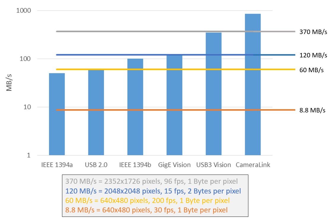
- Bandwidth: With transmission rates of up to 125 Mb/s, Gigabit Ethernet is faster than USB, USB 2, IEEE 1394a, and IEEE 1394b.
Figure 1: Various bus technologies and their bandwidths
- Network Capable: You can setup a network to acquire images from multiple cameras. However, all the cameras share the same bandwidth.
- Future Growth: With 10 Gb and 100 Gb Ethernet standards on their way, the GigE Vision standard can easily scale to use the higher transmission rates available.
Like Ethernet and Fast Ethernet, most of the communication packets on Gigabit Ethernet are transported using either the TCP or the UDP protocol. Transmission Control Protocol (TCP or TCP/IP) is more popular than User Datagram Protocol (UDP) because TCP can guarantee packet delivery and packet in-orderness (i.e. Packets are delivered in the same order that they were sent). Such reliability is possible because packet checking and resend mechanisms are built into the TCP protocol. While UDP cannot guarantee packet delivery or in-orderness, it can achieve higher transmission rates since there is less overhead involved in packet checking.
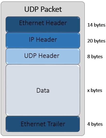
The GigE Vision standard uses the UDP protocol for all communication between the device and the host. A UDP packet consists of an Ethernet Header, an IP Header, a UDP Header, the packet data, and an Ethernet Trailer. The size of the packet data can be up to 1500 bytes. Any data over 1500 bytes is typically broken up into multiple packets. However, for GigE Vision packets, it is more efficient to transmit larger amount of data per packet. Many Gigabit Ethernet network cards support Jumbo Frames. Jumbo frames allow transmission of packet data as large as 9014 bytes.
Figure 2: A UDP Packet
The GigE Vision Standard
The GigE Vision Standard is owned by the Automated Imaging Association(AIA) and was developed by a group of companies from every sector within the machine vision industry with the purpose of establishing a standard that allows camera and software companies to integrate seamlessly on the Gigabit Ethernet bus. It is the first standard that allows images to be transferred at high speeds over long cable lengths.
While Gigabit Ethernet is a standard bus technology, not all cameras with Gigabit Ethernet ports are GigE Vision compliant. In order to be GigE Vision Compliant, the camera must adhere to the protocols laid down by the GigE Vision standard and must be certified by the AIA. If you are unsure whether your camera supports the GigE Vision standard, look for the following logo in the camera documentation.
Figure 3: Official logo for the GigE Vision Standard
The GigE Vision standard defines the behavior of the host as well as the camera. There are four discrete components to this behavior
GigE Vision Device Discovery
When a GigE Vision device is powered on, it attempts to acquire an IP address in the following order:
- Persistent IP: If the device has been assigned a persistent IP, it will assume that IP address.
- DHCP Server: If no IP address is already assigned to the device, it searches the network for a DHCP server and requests the server to assign the device an IP address.
- Link Local Addressing: If the first two methods fail, the device automatically assumes an IP address of the form 169.254.x.x. It then queries the network to check if the IP address is already taken. If it is the only device with that IP address, the device keeps the IP address; otherwise, it picks a new IP address and repeats the process until it finds an IP address that is not already taken.
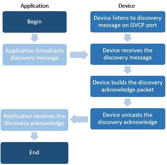
Since cameras can be added to the network at anytime, the driver must have some way to discover new cameras. To accomplish this, the driver broadcasts a discovery message over the network periodically. Each GigE Vision compliant device responds with its IP address.
The following algorithm describes the device discovery process.
Figure 4: Device discovery flowchart
GigE Vision Control Protocol (GVCP)
GVCP allows applications to configure and control a GigE Vision device. The application sends a command using the UDP protocol and waits for an acknowledgment (ACK) from the device before sending the next command. This ACK scheme ensures data integrity. Using this scheme, the application can get and set various attributes on the GigE Vision device, typically a camera.
The GigE Vision standard defines a minimal set of attributes that GigE Vision devices must support. These attributes, such as image width, height, pixel format, etc., are required to acquire an image from the camera and hence are mandatory. However, a GigE Vision camera can expose attributes beyond the minimal set. These additional attributes must confirm to the GenICam standard.
GenICam
GenICam provides a unified programming interface for exposing arbitrary attributes in cameras. It uses a computer readable XML datasheet, provided by the camera manufacturer, to enumerate all the attributes. Each attribute is defined by its name, interface type, unit of measurement and behavior.
GenICam compliant XML datasheets eliminate the need for custom camera files for each camera. Instead, the manufacturer can describe all the attributes for the camera in the XML file so that any GigE Vision driver can control the camera. Additionally, the GenICam standard recommends naming conventions for features such as gain, shutter speed, and device model that are common to most cameras.
GigE Vision Stream Protocol (GVSP)
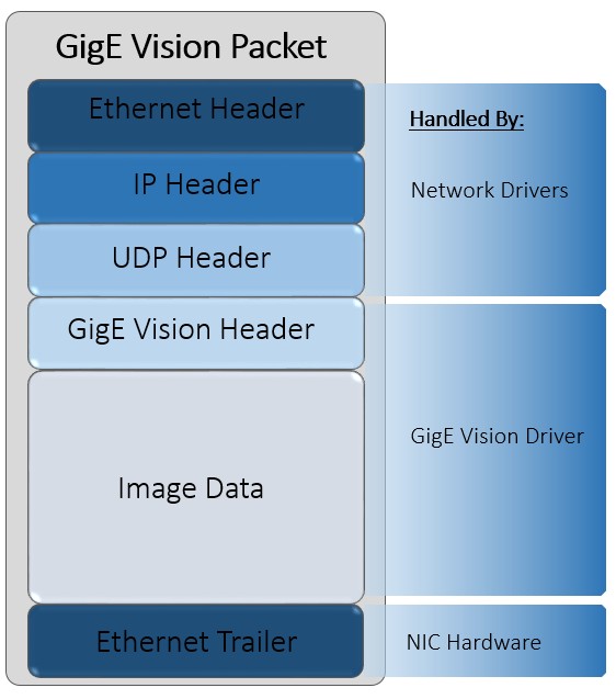
The GigE Vision standard uses UDP packets to stream data from the device to the application. The device includes a GigE Vision header as part of the data packet that identifies the image number, packet number, and the timestamp. The application uses this information to construct the image in user memory.
Figure 5: A GigE Vision Packet
Packet loss and resends
Since image data packets are streamed using the UDP protocol, there is no protocol level handshaking to guarantee packet delivery. Therefore, the GigE Vision standard implements a packet recovery process to ensure that images have no missing data. However, this packet recovery implementation is not required to be GigE Vision compliant. While most cameras will implement packet recovery, some low-end cameras may not implement it.
The GigE Vision header, which is part of the UDP packet, contains the image number, packet number, and timestamp. As packets arrive over the network, the driver transfers the image data within the packet to user memory. When the driver detects that a packet has arrived out of sequence (based on the packet number), it places the packet in kernel mode memory. All subsequent packets are placed in kernel memory until the missing packet arrives. If the missing packet does not arrive within a user-defined time, the driver transmits a resend request for that packet. The driver transfers the packets from kernel memory to user memory when all missing packets have arrived.
The NI-IMAQdx driver
The NI-IMAQdx driver is included in Vision Acquisition Software 8.2.1 and higher. Please visit the Drivers page for the latest version of the software. The NI-IMAQdx driver supports IIDC compliant IEEE 1394 (Firewire) cameras, GigE Vision compliant Gigabit Ethernet cameras, and USB3 Vision USB 3.0 cameras within a unified API. This section specifically discusses the architecture of the GigE Vision part of the driver.
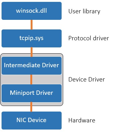
In order to better understand the GigE Vision part of the NI-IMAQdx driver, we must first understand the underlying structure of the Windows Network Driver Stack.
Figure 6: The Windows Network Driver Stack
- User Library : The Winsock library handles calls from user level applications. It provides an easy API to handle network communication. Functions in the Winsock layer call corresponding functions in the protocol driver.
- Protocol driver: tcpip.sys implements the TCP and UDP protocols. Based on the protocol being used, this driver handles all the packet management required.
- Device driver: This layer is divided into two parts. The Intermediate driver is a hardware agnostic Windows driver that translates commands to and from the miniport driver. The miniport driver is a hardware specific, vendor provided driver that can communicate with the intermediate driver. The miniport driver translates generic intermediate driver calls to hardware specific calls to the device. Each Network Interface Card (NIC) has a separate miniport driver. The miniport driver allows different NIC devices to communicate with the intermediate driver using a universal API.
- Hardware: The NIC Device is the physical layer that sends and receives data packets over the network.
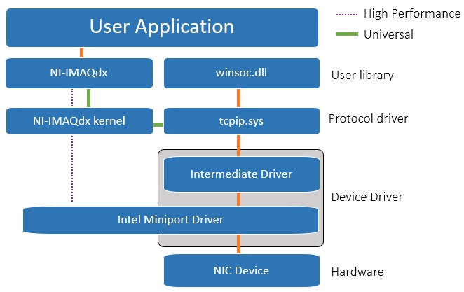
When a GigE Vision image data packet arrives over the network, it can reach the user application using one of two flavors of the NI-IMAQdx driver: the High Performance driver or the Universal driver
Figure 7: The NI-IMAQdx driver stack
Universal Driver
When a image data packet arrives, it follows the same path as any other network packet until it is handled by the Protocol driver. Then the packet is passed to the NI-IMAQdx driver which extracts the image data and passes it to the user application.
High Performance Driver
The high performance driver was developed to circumvent the overhead within the Windows Network Driver Stack. Since the universal driver must use the intermediate driver and the protocol driver to communicate with the hardware specific miniport driver, it requires more CPU processing. The high performance driver bypasses the intermediate driver and protocol driver by communicating directly with the miniport driver. However, the high performance driver will only work with the miniport driver for Intel's Pro 1000 chipset. The NI-IMAQdx kernel implements the protocol driver to handle TCP and UPD packets.
Advantages
While the high performance driver provides better CPU performance compared to the universal driver, it will only work on Gigabit Ethernet cards with the Intel Pro 1000 chipset. The universal driver can work on any Gigabit Ethernet card recognized by the operating system. CPU usage during acquisition will affect the CPU cycles available for image analysis. So, if your application requires in-line processing, it is better to invest in a Gigabit Ethernet card with the Intel Pro 1000 chipset. While your choice of driver affects the CPU usage, it does not limit the maximum bandwidth possible. Either driver will be able to achieve the maximum bandwidth of 125 MB/s.
High Performance Driver vs. Universal Driver
| Network Card Chipset | CPU usage | Max Bandwidth |
| High Performance Driver | Intel Pro 1000 | Best | 125 MB/s |
| Universal Driver | Any chipset | Good | 125 MB/s |
Caveats
-
Dedicated Networks: While GigE Vision cameras can work on a common corporate network (used for email, web, etc), it is highly encouraged that you use a dedicated network for machine vision.
-
CPU Usage: Unlike other machine vision bus technologies, which can DMA images directly into memory, Gigabit Ethernet requires CPU usage for packet handling. This means that you are left will fewer CPU cycles to perform image analysis. While CPU usage can be mitigated to a certain extent by using the high performance driver, it cannot be eliminated.
-
Maximum Bandwidth: While the theoretical bandwidth of Gigabit Ethernet is 125 MB/s, due to packet transmission overhead, you can reasonably expect only about 120 MB/s in a point-to-point network (one computer, one camera; directly connected). Networks with multiple cameras and hubs will increase overhead and decrease the bandwidth.
-
Latency: Because network packets can get lost, requiring resends and network packet handling is CPU dependent, there is a non-trivial latency between the time a camera captures an image and the time it appears in user memory.
