Camera Link Tap Geometry Explained
Overview
Contents
To use the Camera link standard and obtain an image, you must first understand tap geometry. Tap geometry is the geometry the camera sensor uses to output data. This might be unique to each camera.
It is important to have this information to make sure you are using a compatible frame grabber that can interpret the data coming from the camera as well as a driver that can arrange the pixels to form an image.
TapGeometry: an enumerated type of parameter that summarizes the configuration that pixels are collected from a camera to build an image. A tap is defined as a pixel being transferred at each cycle of the pixel clock.
Tap Geometry Naming Convention
A tap geometry for area-scan camera is designated by: <TapGeometryX>-<TapGeometryY>
A tap geometry for line-scan or TDI-line-scan camera is designated by: <TapGeometryX>
TapGeometryX is designated by <RegionX>X<TapX>
- <RegionX>: an integer in range {1, 2, 3, 4, 8, 10} declaring the number of regions encountered across the horizontal direction. A region is a rectangular area of adjacent pixels that are transferred in a raster-scan order through one or several taps. In case of several taps, adjacent pixels are transferred simultaneously.
- <TapX>: an integer in range {2, 4, 8, 10} declaring the number of consecutive pixels across horizontal direction that are output simultaneously from a region. This field is omitted when all pixels are in the same column.
TapGeometryY is designated by <RegionY>Y<TapY>
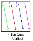
- <RegionY>: an integer in range {1, 2, 4, 8, 10} declaring the number of regions encountered across vertical direction.
- <TapY>: an integer declaring the number of consecutive pixels across vertical direction that are output simultaneously from a region. This field is omitted when all pixels are in the same line.
Examples
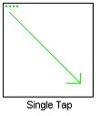
- 1X-1Y designates an area-scan camera having 1 region across X and 1 region across Y. The pixels are delivered one at a time on a single tap beginning with the leftmost pixel of the top line.
- 1X4 designates a line-scan camera having 1 region across X. Four adjacent pixels are delivered simultaneously on 4 taps beginning with the leftmost pixels.
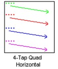
- 4X1 designates a line-scan camera having 4 regions across X. Four non-adjacent pixels are delivered simultaneously on 4 taps; all taps begins with the leftmost pixel.
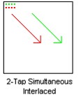
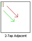
- This is an interesting one. Let's just take it one step at a time. For the X axis, there are still just one zone with 2 taps. So two taps per zone. The Y axis is simpler. There’s only one zone vertically. Therefore, its 1X2-1Y1
Restrictions
- All zones have the same size. Zones are not overlapping. All zones have the same number of taps. All taps are carrying the same number of pixels.
- 1X1 1X1-1Y2
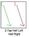
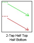
- 1X2-1Y 2X1-1Y
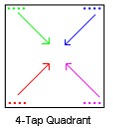
- 1X1-2Y1 2X1-2Y1(directions of arrows not represented) 1x1-4Y1 1X1-1Y4
