Case Structure
- Updated2025-07-30
- 3 minute(s) read
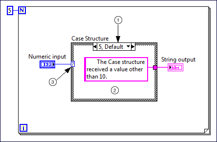
Contains one or more subdiagrams, or cases, exactly one of which executes when the structure executes. The value wired to the case selector determines which case to execute.

Components of a Case Structure
 |
 |
 Selector label—Displays the value(s) for which the associated case executes. You can specify a single value or a range of values. You also can use the selector label to specify a default case.
  Subdiagram(case)—Contains the code that executes when the value wired to the case selector matches the value that appears in the selector label. To modify the number or order of subdiagrams, right-click the border of the Case structure and select the appropriate option.
  Case selector—Selects which case to execute based on the value of the input data. The input data can be a Boolean, string, integer, enumerated type or error cluster. The data type you wire to the case selector determines the allowed cases you can enter in the selector label.
 Configuring a Case Structure
Rearranging a Case Structure
Troubleshooting a Case Structure
FPGA Module Details
The following details apply when you use this object in an FPGA VI.
| Single-Cycle Timed Loop | Supported. |
| Usage | N/A |
| Timing | Inside single-cycle Timed Loop--When you use a Case structure inside a single-cycle Timed Loop, the combinatorial logic delay required to evaluate the case selector is proportional to the width of the selector input data type and the number of cases. The combinatorial logic delay introduced by output tunnels is proportional to the number of cases. Outside single-cycle Timed Loop--When you use a Case structure outside a single-cycle Timed Loop, it takes one clock cycle to evaluate the case selector. Output tunnels require no clock cycles to execute and never include a register. |
| Resources | The case selector requires FPGA resources proportional to the width of the input data type and the number of cases. Output tunnels require FPGA resources proportional to the width of the output data type and the number of cases. |
| Notes | Complex Case structures can lead to long combinatorial paths and limit the maximum clock rate of a clock domain. |
Examples
Refer to the following example files included with LabVIEW.
- labview\examples\Structures\Case Structure\Case Structure - Selector Data Types.vi