Adding and Configuring Components of a Screen
- Updated2025-01-27
- 1 minute(s) read
Adding and Configuring Components of a Screen
Add controls and indicators to a Screen to modify the user interface of a VeriStand project.
The following image highlights the parts of the VeriStand Editor you use to add and configure controls and indicators.
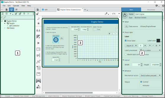
| 1 |
System Definition palette—A palette that displays the targets and channels in the current system definition file. You can drag channels from the System Definition palette and drop them onto the screen to add controls and indicators for those channels. VeriStand selects an appropriate control or indicator type for the channel. |
| 2 | Controls and indicators—Objects you add to the screen to either enter or view data from the system definition. Each control or indicator can accept or display a single type of data, such as a number, a TRUE/FALSE value, or a text string. |
| 3 | Item tab—Collection of options for customizing a selected control or indicator. The options on the Item tab appear only when you select a control or indicator on a screen. |