Three-Phase Inverter (Electric Motor Simulation Toolkit)
- Updated2023-02-21
- 5 minute(s) read
Three-Phase Inverter (Electric Motor Simulation Toolkit)
An inverter is an electrical device that converts direct current (DC) to alternating current (AC). A three-phase inverter is a commonly-used inverter for powering a variable-speed motor like the permanent magnet synchronous motor (PMSM). The three-phase inverter consists of three single-phase branches which connect to three load terminals. Each single-phase branch contains two power switches. The following figure illustrates the circuit diagram of a three-phase inverter. In this circuit, the three resistances represent the load. In real applications, the load can be an electric motor.
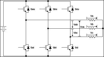
The following symbols apply to the circuit diagram:
- Sau is the phase A upper switch.
- Sal is the phase A lower switch.
- Sbu is the phase B upper switch.
- Sbl is the phase B lower switch.
- Scu is the phase C upper switch.
- Scl is the phase C lower switch.
- Vab, Vbc, and Vca are the line-to-line voltages.
- Va, Vb, and Vc are the phase voltages.
The Electric Motor Simulation Toolkit allows you to simulate an ideal three-phase inverter or an advanced three-phase inverter. In the ideal three-phase inverter model, the switches are simple on-off switches. When the switch is on, no voltage drop happens on the switch. When the switch is off, no current flows through the switch. In the advanced three-phase inverter model, the switches are insulated gate bipolar transistors (IGBT) with diodes. The advanced three-phase inverter model simulates the transient behavior of the inverter. By using the advanced three-phase inverter model, you can specify the forward voltage drops of the switches and insert fault to the inverter at run time.
Ideal Three-Phase Inverter Model
The ideal three-phase inverter model assumes that the switch state changes between on and off instantaneously. The two switches in the same single-phase branch are complementary. The following table lists the phase voltages and line-to-line voltages of the ideal three-phase inverter model. VDC is the DC voltage that connects to the inverter. In the Switch State column, 1 indicates that the switch is on, while 0 indicates that the switch is off.
| Switch State | Phase Voltage (V) | Line-to-Line Voltage (V) | ||||||
|---|---|---|---|---|---|---|---|---|
| Sau | Sbu | Scu | Va | Vb | Vc | Vab | Vbc | Vca |
| 0 | 0 | 0 | 0 | 0 | 0 | 0 | 0 | 0 |
| 1 | 0 | 0 | 2VDC/3 | -VDC/3 | -VDC/3 | VDC | 0 | -VDC |
| 1 | 1 | 0 | VDC/3 | VDC/3 | -2VDC/3 | 0 | VDC | -VDC |
| 0 | 1 | 0 | -VDC/3 | 2VDC/3 | -VDC/3 | -VDC | VDC | 0 |
| 0 | 1 | 1 | -2VDC/3 | VDC/3 | VDC/3 | -VDC | 0 | VDC |
| 0 | 0 | 1 | -VDC/3 | -VDC/3 | 2VDC/3 | 0 | -VDC | VDC |
| 1 | 0 | 1 | VDC/3 | -2VDC/3 | VDC/3 | VDC | -VDC | 0 |
| 1 | 1 | 1 | 0 | 0 | 0 | 0 | 0 | 0 |
The Electric Motor Simulation Toolkit only calculates the phase voltages. The following equations demonstrate the relationship between the line-to-line voltages and the phase voltages.


Advanced Three-Phase Inverter Model
The advanced three-phase inverter model regards the IGBT-with-diode switch as a small inductance (L) when the switch is on. When the switch is off, the model regards the switch as a small capacitance (C). A conductance (G) in parallel with a dependent current source (J) represents a switch. The following figure illustrates how the advanced three-phase inverter model simulates the switch.

The advanced three-phase inverter model regards the conductance as a constant to simplify the calculation process. The following equations show the relationship between the conductance and the simulation time interval (dt).


The following equation determines the current source. The subscript k and k-1 denote the simulation steps.
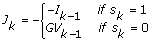
| where | Ik-1 is the current on the switch at the k-1 step |
| Vk-1 is the voltage on the switch at the k-1 step | |
| sk=1 denotes that the switch is on at the k step | |
| sk=0 denotes that the switch is off at the k step |
The following equation determines the state of the IGBT-with-diode switch.

where  denotes the complement of s. g is the gate signal for the switch. g=1 denotes that the gate signal commands the switch to be on, while g=0 denotes that the gate signal commands the switch to be off.
Inserting Fault to the Inverter
The advanced three-phase inverter model allows you to simulate the behavior of an inverter when the switch has faults. The model provides four types of faults and only supports one fault at a time. The four fault types are as follows.
- IGBT open fault—This fault occurs if any IGBT is interrupted. No current flows through the IGBT with fault. It is equivalent to replacing the switch with a diode.
- Diode open fault—This fault occurs if any diode is interrupted. No current flows through the diode with fault. It is equivalent to replacing the switch with an IGBT.
- IGBT and diode open fault—This fault occurs if any IGBT-with-diode switch is interrupted. No current flows through the IGBT-with-diode switch with fault. It is equivalent to removing the switch from the circuit.
- IGBT or diode short fault—This fault occurs if any IGBT or diode is bypassed. It is equivalent to replacing the switch with a wire. In this case, the protection circuit turns off the other switch in the same single-phase branch as the switch with fault. As a result, short circuit does not happen to the voltage source.