Constant Parameter Model (Electric Motor Simulation Toolkit)
- Updated2023-02-21
- 6 minute(s) read
Constant Parameter Model (Electric Motor Simulation Toolkit)
Use the constant parameter model function to simulate an AC induction motor (ACIM) or a permanent magnet synchronous motor (PMSM).
Constant Parameter Model for ACIM Simulation
The constant parameter model simulates the electromagnetic behavior of an ACIM by using the (α,β) orthogonal coordinate system.
In an (α,β) orthogonal coordinate system, the α axis usually coincides with the direction of the A current of the three-phase current in the stator. The β axis is the axis at an angle of 90 degrees from the α axis.
The following figure illustrates the relationship between the (α,β) orthogonal coordinate system and the three-phase current.

Because of the three-phase current in the stator windings, the magnetizing currents of the stator produce a magnetic field. The magnetic field generates a current in the rotor. The voltage equations for ACIM simulation with the constant parameter model are as follows.


| where | Vsα is the stator voltage along the α axis |
| Vsβ is the stator voltage along the β axis | |
| Rs is the stator resistance | |
| Isα is the stator current along the α axis | |
| Isβ is the stator current along the β axis | |
| λsα is the stator flux linkage along the α axis | |
| λsβ is the stator flux linkage along the β axis | |
| Vrα is the rotor voltage along the α axis | |
| Vrβ is the rotor voltage along the β axis | |
| Rr is the rotor resistance | |
| Irα is the rotor current along the α axis | |
| Irβ is the rotor current along the β axis | |
| λrα is the rotor flux linkage along the α axis | |
| λrβ is the rotor flux linkage along the β axis | |
| ωr is the electrical speed, in rad/s, which equals to rotor speed times the number of pole pairs |
The flux linkage equations are as follows.


| where | Lls is the stator leakage inductance |
| Llr is the rotor leakage inductance | |
| Lm is the magnetizing inductance |
The voltage equations calculate the derivatives of stator flux linkage and rotor flux linkage.


where k and k-1 are the simulation steps. For example, λsα(k) is the stator flux linkage along the α axis at the k step, while λsα(k-1) is the stator flux linkage along the α axis at the k-1 step.
The flux linkage equations calculate the current by defining λmα, λmβ, and LM.

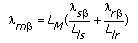

The following equations can be derived to obtain the current in the (α,β) orthogonal coordinate system.


The constant parameter model calculates the electric torque of an ACIM by using the following equation.

where p is the number of poles.
Constant Parameter Model for PMSM Simulation
The constant parameter model simulates the electromagnetic behavior of a PMSM by using the d-q axes mathematical method.
The d-q axes are the axes in a (d,q) coordinate system. The d axis, or the direct axis, usually coincides with the axis of the rotor magnet pole. The q axis, or the quad axis, is the axis at an angle of 90 degrees from the d axis. When the rotor is stationary, the (d,q) coordinate system is a stationary reference frame. When the rotor starts rotating, the system is a rotor reference frame where the (d,q) coordinate system rotates at the rotor speed.
The following figure illustrates a (d,q) coordinate system.

While the rotor is rotating, electromagnetic current is generated inside the electric motor. The voltage equations of the (d,q) rotor reference frame are as follows.


The flux linkage equations are as follows.
λd=LdId+λf
λq=LqIq
| where | ωr is electrical speed, in rad/s, which equals to rotor speed times the number of pole pairs |
| Id is the current along the d axis | |
| Iq is the current along the q axis | |
| λd is the flux linkage along the d axis | |
| λq is the flux linkage along the q axis | |
| λf is the flux linkage in the rotor magnet | |
| Ld is the inductance along the d axis | |
| Lq is the inductance along the q axis |
The following equation calculates the electric torque of the (d,q) rotor reference frame.

where p is the number of poles.
The following discrete equations calculate the current for PMSM simulation with the constant parameter model.


where k and k-1 are the simulation steps. For example, Id(k) is the current along the d axis at the k step, while Id(k-1) is the current along the d axis at the k-1 step.