GPIB Read Function
- Updated2025-03-14
- 5 minute(s) read
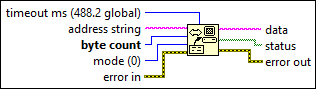
GPIB Read Function
Reads byte count number of bytes from the GPIB device at address string.
Right-click the node and select Synchronous I/O Mode»Synchronous from the shortcut menu to read data synchronously.
Inputs/Outputs
 timeout ms (488.2 global)
—
timeout ms (488.2 global)
—
timeout ms specifies the time, in milliseconds, that the function waits before timing out. The operation aborts if it does not complete within timeout ms. To disable timeouts, set timeout ms to 0. To use the 488.2 global timeout, leave timeout ms unwired or set the input to –1. Then use the SetTimeOut function to change the default value of timeout ms. The default is 10000.  address string
—
address string
—
address string contains the address of the GPIB device with which the function communicates. You can input both the primary and secondary addresses in address string by using the form primary+secondary. Both primary and secondary are decimal values, so if primary is 2 and secondary is 3, address string is 2+3. If you do not specify an address, the functions do not perform addressing before they attempt to read and write the string. They assume you have either sent these commands another way or that another controller is in charge and therefore responsible for the addressing. If the controller is supposed to address the device but does not do so before the time limit expires, the functions terminate with GPIB error 6 (timeout) and set bit 14 in status. If the GPIB is not the Controller-In-Charge, do not specify address string. When there are multiple GPIB controllers that LabVIEW can use, a prefix to address string in the form ID:address (or ID: if no address is necessary) determines the controller that a specific function uses. For example, to set GPIB controller 2 to talk to a device on address 3, use the prefix 2:3. If a controller ID is not present, the function defaults to controller (or bus) number 0.
byte count
—
byte count specifies the number of bytes the function reads from the GPIB device.  mode (0)
—
mode (0)
—
mode specifies conditions, other than reaching byte count, for terminating the read. The following table includes valid values and the corresponding EOS characters. Any mode not listed in the table indicates the decimal number of the EOS character that you want. Refer to >GPIB Multiline Interface Messages for more information about managing GPIB tasks.
 error in
—
error in
—
error in describes error conditions that occur before this node runs. This input provides standard error in functionality.  data
—
data
—
data is the data the function read.  status
—
status
—
status is a Boolean array in which each bit describes a state of the GPIB Controller. If an error occurs, the function sets bit 15. GPIB error is valid only if bit 15 of status is set. The following table shows the numeric value and symbolic status of each bit in status. This table also includes a description of each bit.
 error out
—
error out
—
error out contains error information. This output provides standard error out functionality. |
When you transfer data from or to a hardware driver synchronously, the calling thread is locked for the duration of the data transfer. Depending on the speed of the transfer, this can hinder other processes that require the calling thread. However, if an application requires that the data transfer as quickly as possible, performing the operation synchronously dedicates the calling thread exclusively to this operation.
The GPIB Read function terminates when it accomplishes one of the following tasks:
- Reads the number of bytes requested.
- Detects an error.
- Exceeds the time limit.
- Detects the END message (EOI asserted).
- Detects the EOS character (if this option is enabled by the value supplied to mode).
Examples
Refer to the following example files included with LabVIEW.
- labview\examples\Instrument IO\GPIB\Simple GPIB.vi