Using Fault Insertion Units (FIUs) for Electronic Testing
Overview
Hardware fault insertion (also known as fault injection) is a critical consideration in test systems that are responsible for the reliability of embedded control units. This tutorial describes the uses for fault insertion as well as how to incorporate fault insertion units (FIUs) into hardware-in-the-loop (HIL) test systems built with PXI hardware. For more information on NI products for fault insertion, visit the FIU selection page.
Contents
- Why Is Hardware Fault Insertion Needed?
- Anatomy of a Fault Insertion Unit
- Benefits of PXI-Based FIUs
- Integrating PXI FIUs into HIL Test Systems
Why Is Hardware Fault Insertion Needed?
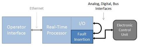
In many hardware-in-the-loop (HIL) test systems, hardware fault insertion is used to create signal faults between the electronic control unit (ECU) and the rest of the system to test, characterize, or validate ECU behavior under specific failure conditions. Fault insertion is most commonly used when it is imperative for a specific ECU to have both a known and an acceptable response to fault conditions – examples include ECUs for vehicles, aircraft, spacecraft, and machinery. To accomplish this, fault insertion units (FIUs) are inserted between the I/O interfaces of a test system and the ECU so the test system can switch between normal operation and fault conditions such as a short to battery, short to ground, or open circuit.
The Figure 1 diagram shows how an FIU typically fits into an HIL test system. Notice that the fault insertion acts as a gate between the I/O and the ECU.
Figure 1. Typical Placement of a Fault Insertion Unit in a Dynamic Test System
Anatomy of a Fault Insertion Unit
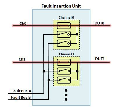
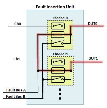
A common configuration for an FIU is a “fault bus topology,” where you can open or short each channel to one or more fault buses. In this topology, each FIU channel consists of three single-pole-single-throw (SPST) relays. The first relay of the channel acts as a pass-through – during the default mode of operation, this relay is closed, and the FIU is transparent to both the ECU and the test system.
Figure 2. An FIU in the Default Mode of Operation – All Signals Are Passed Through
Open Circuit Faults
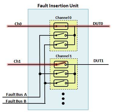
To simulate an open circuit or interrupt fault, the signal line between the test application and device under test (DUT) is left open to determine how the DUT behaves after a signal interruption. You can open this relay to simulate a hard break or open and close it at a specified time interval to simulate an intermittent connection or loose contacts.
Figure 3. An FIU with an Open-Circuit Simulation on Channel 1
Short to Ground or Short to Power
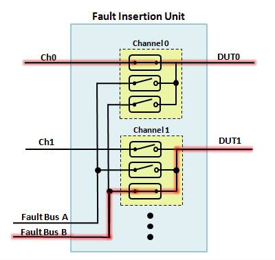
To simulate shorts to ground or power, the signal line is connected from an external fault line or fault bus to the DUT. You can configure the fault buses to simulate power supply lines, system ground, or other power sources in the system.
Figure 4. An FIU with a Short-to-Power Fault Simulation on Channel 1
Pin-to-Pin Shorts
Finally, to simulate a pin-to-pin short, the DUT signal line is connected to one or more additional DUT signal lines.
Figure 5. An FIU with a Pin-to-Pin Short between Channels 0 and 1
Benefits of PXI-Based FIUs
With its triggering and synchronization features, PXI provides an ideal environment for FIUs. And because HIL test systems are commonly architected with PXI-based I/O, PXI also offers close proximity to the signals you need to switch. Such systems are commonly controlled via embedded real-time processing software such as NI VeriStand, so having a PXI-based FIU makes it simple for engineers to programmatically select and control faults from the same interface that is running their model and test sequences.
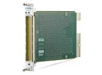
National Instruments recently released its first FIU, the NI PXI-2510, a 68-channel, 150 V, 2 A FIU designed for use in HIL applications. Each module has 68 feedthrough channels that you can open or short to one or two fault buses. Additionally, each fault bus has a 4x1 input multiplexer, thereby allowing greater flexibility for both the type and number of faults that you can inject via software control.
Figure 6. NI PXI-2510 68-Channel 2 A FIU
In addition to easy integration with HIL test systems, NI PXI FIUs offer the hardware-related advantages of safety, reliability, and connectivity.
Safety
Because high voltages and currents are often associated with fault insertion, and reliability is essential for HIL applications, NI takes the utmost care with its FIUs when it comes to safety. Specifically, all NI FIUs are compliant with IEC 61010-1 international standards, and have had their designs verified through third-party agencies such as UL. Finally, each unit is tested prior to shipping to validate both functionality and safety.
Reliability
Similar to safety, reliability is a key concern for the integrity of long-term tests. Although rated for millions of cycles, electromechanical relays have a finite and relatively predictable lifetime under normal loading conditions. To allow for increased long-term reliability, the PXI-2510 incorporates onboard relay count tracking, which you can use to view the number of cycles each relay has undergone. This helps you determine your maintenance and replacement needs. The PXI-2510 features a user-replaceable relay kit in the event of normal relay failure at the end of its specified lifetime. NI also recognizes that through the course of usage, unforeseen circumstances can result in the accidental damage of relays by exposure to excessive voltages and currents, in which case the user-replaceable relay kit is also valuable. Finally, for mechanical reliability, each FIU design undergoes highly accelerated life test (HALT) screening to ensure mechanical soundness in high-vibration environments, which allows for sustained use in harsh field conditions.
Connectivity
Often overlooked, cabling and connectivity are major concerns for fault insertion applications due to the potentially large number of channels involved as well as the high voltages and currents that you can use. The PXI-2510 offers three connectivity options – screw terminal, bare wire, and DIN connector. Each of these options has been specifically designed to guarantee safety, reliability, and shielding all the way to the signal terminals to provide a full connectivity solution. The result is improved noise and crosstalk in addition to reduced system emissions.
To learn more about connectivity and cabling options for the PXI-2510, visit the “How to Connect Signals to the PXI-2510" tutorial.
In addition to products specifically designed for fault insertion, National Instruments offers a variety of general-purpose switching products that you can use to create custom fault insertion topologies. An example is the NI PXI-2586 10-channel, 12 A SPST module, which you can use to create multiple topologies for fault insertion, including a three-channel, two-bus FIU and a nine-channel, one-bus FIU, as shown in this tutorial.
Integrating PXI FIUs into HIL Test Systems
System integration, including software, is a final key consideration when choosing an FIU. In the Windows environment, you can interactively configure and test PXI FIUs through the NI-SWITCH Soft Front Panel (SFP) – a graphical utility designed for switch debugging. For automated control, the included NI-DAQmx hardware driver provides programmatic access to the full functionality of the module through the LabVIEW Real-Time and Windows OSs.
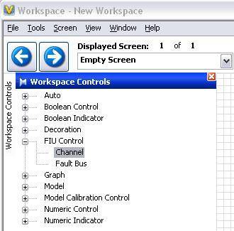
Most commonly, HIL test systems are controlled via NI VeriStand, a ready-to-use software environment for configuring real-time testing applications. You can easily control NI PXI FIUs with NI VeriStand, which means you can manage them in the same environment that you use to configure real-time I/O, stimulus profiles, data logging, and alarming; implement control algorithms or system simulations; build test system interfaces for a run-time editable user interface; and more.
Figure 7. NI VeriStand Control of FIUs
For more advanced and time-sensitive control, each FIU module can send and receive triggers through the PXI backplane. Input triggers can advance the switch to the next fault location in a predefined list loaded onto the FIU hardware. You can use output triggers to initiate measurements on other instruments in the PXI system. You also can send triggers from real-time simulations to sequence through fault conditions for automated test coverage or, for applications requiring more complex sequencing and dynamic fault control, you can use a PXI field-programmable gate array (FPGA) module to send and receive triggers to one or more FIUs via the PXI backplane.
Conclusion
When ECU reliability is essential, you should consider FIUs. NI has created a hardware and software architecture you can use to integrate FIUs into HIL test systems in order to improve device safety and reliability.
