
5 RF Transmitter Measurements Engineers Should Know
BUSINESS INSIGHT
WIRELESS | 12 MINUTE READ
RF transmitters are an essential part of modern communications. Designed and assembled from core RF components, RF transmitters have many different forms and applications.
RF transmitters are an essential part of modern communications. Designed and assembled from core RF components, RF transmitters have many different forms and applications. We often think of RF transmitters in wireless communications, but the concept applies equally to wired applications such as cable television. Cellular phones, radar, military communications, avionics, wireless LAN, modems, and signal generators are just a few examples of systems that employ one or more RF transmitters.
Operating parameters, cost, and design considerations impact RF transmitter performance and, subsequently, the RF signal quality. Consequently, ensuring the RF transmitter meets specification is essential in quality RF communications. Across various implementations of RF transmitters there are standard tests that are essential to ensuring proper operation. This paper explores five essential measurements frequently performed on RF transmitters.
RF Output Power
The most common RF transmitter measurement is RF power. Before performing any other tests, the engineer wants to know, “Is my DUT outputting power? Is it outputting power within specified parameters?” Testing RF power answers these questions and is the first indication of the system’s health.
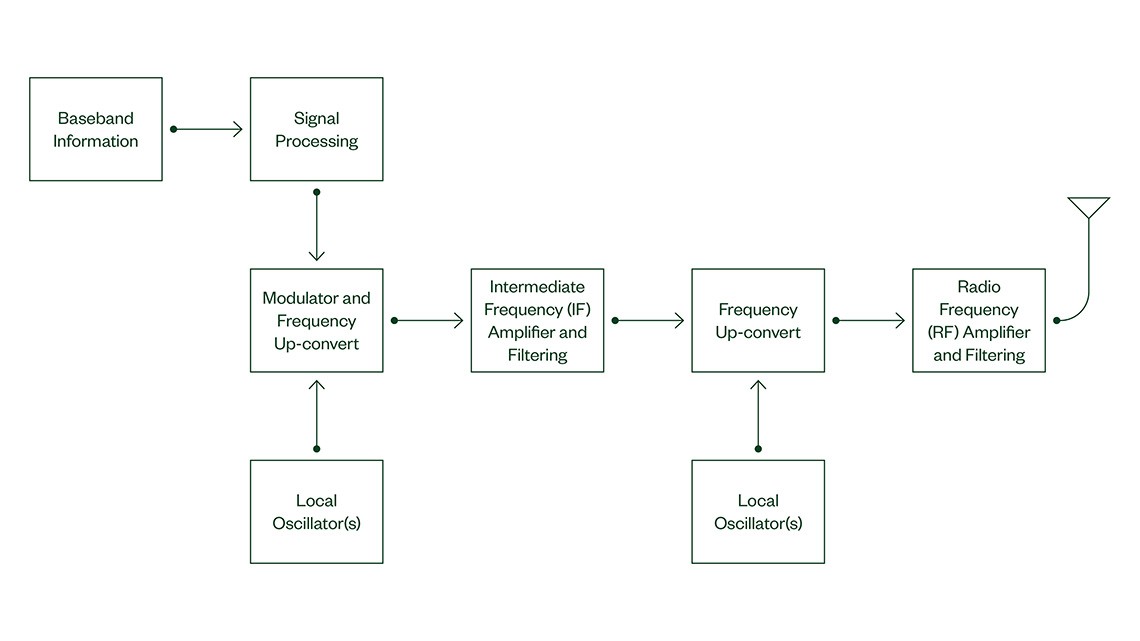

One accurate and cost-effective instrument for measuring RF power is the RF power meter. Because it’s a scalar instrument, incapable of measuring phase, care should be taken to minimize impedance mismatches whose reflections can add in and out of phase with the signal being measured, resulting in greater magnitude uncertainty. Power meters are broadband and not frequency selective, so any unwanted signals are averaged into the desired measurement. The dynamic range of most power meters is 50 to 70 dB. High-end power meters are capable of specialized measurements such as integrated power across a band and triggering for pulsed RF power. For these reasons, power meters are a good choice if the RF environment is well controlled.
Another instrument commonly used to measure RF power is a spectrum analyzer. With these more complex RF instruments, engineers can measure the individual spectral components across frequency. The absolute power measurement accuracy is not outstanding, typically + 0.5 to + 2.0 dB. However, the relative power accuracy (or amplitude linearity) is excellent. Therefore, calibrating at a given frequency with a known power level, from a signal generator, for example, results in corrected power measurements that are accurate across a dynamic range greater than 100 dB.
High-performance RF instruments, including vector signal analyzers and vector network analyzers, can measure magnitude and phase, offering the potential for greater error correction and measurement accuracy. In addition to the RF power measurements mentioned previously, specialty measurements can be made on pulsed and other complex RF waveforms. This includes pulse profiling, which measures the power across the envelope of an RF pulse, along with the average and peak power of the RF pulse. Complex IQ waveforms are measured in more of a noise-like fashion with measurements such as peak-to-average ratio, and complementary cumulative distribution function (CCDF).

Power in a Band
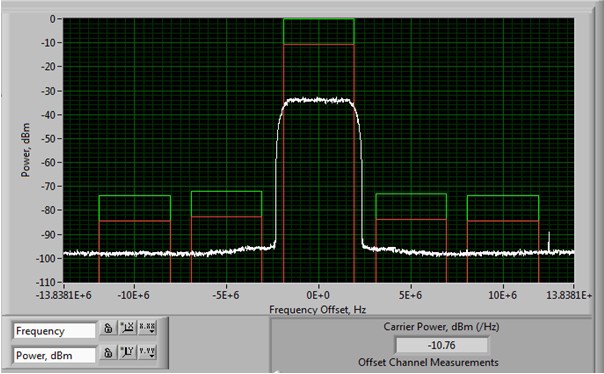
To improve spectral efficiency and permit multiple users for a given spectrum, RF transmitters use a variety of modulation techniques to encode and send information. Modern communications are allocated a specific amount of frequency spectrum, often referred to as a “channel.” The channel is usually defined by a regulating body, such as the Federal Communications Commission (FCC) in the United States. Users are generally concerned with two measurements with regard to their assigned spectrum. One measurement is the integrated power across the assigned channel, often called the occupied bandwidth (OBW), power-in-band, or channel power. Here the power is integrated across the channel from the assigned start to the assigned stop frequency.
In addition to measuring the power in the channel, there is also a need to ensure that transmissions are not leaking into channels assigned to other users, especially those on either side of the assigned channel. In addition to technical shortcomings, this can result in costly fines from regulatory agencies. A typical test approach is to fill the assigned (occupied) band with a test signal and measure the integrated power versus frequency in the channels adjacent to the occupied channel. This test goes by many names, but it’s generically referred to as the adjacent channel power (ACP) measurement. The exact frequencies, integrated power specifications, and test methods are specified by the standards governing the transmission.
Unwanted Signals
With a perfect RF transmitter, the only signal transmitted would be the signal of interest. However, unwanted signals are a consequence of real-world transmitter design trade-offs. Cost, performance, and other requirements influence the final product. These unwanted signals fall within three broad categories: harmonic, intermodulation, and spurious (spurs).
Signals that are integer multiples of the main carrier signal are said to be harmonically related. Leading sources of these signals are amplifiers used in the transmitter. These signals may be low enough in amplitude so they aren’t considered significant. Or, they may be far enough away in frequency that they can be reduced with filtering. Harmonics are easy to detect because their frequency is predictable. For example, the harmonic content of a signal at 1 GHz, can be found at 2 GHz, 3 GHz, and so on.
Intermodulation products are signals generated by nonlinear interactions in the transmitter components. Mixers are an example of a circuit component with nonlinear behavior. The mixer outputs the sum and difference of the two input signal frequencies. In RF transmitters, the output is filtered to isolate the higher frequency sum in a process known as upconversion. In this way, through one or more upconversion stages, the low-frequency baseband information can be translated to the final RF frequency for transmission. Unfortunately, mixers also provide a host of other signals including combinations of the input signals and their harmonics, as well as leakage of the input signals to the output. The frequency and amplitude of the intermodulation products change with changes in the input signals. With careful analysis, intermodulation products can be predicted, making it possible to minimize their impact.
The term spurious or spur is often applied to any unwanted signal. In the context of this paper, it refers to any unwanted signal not discussed above. Spurs can occur at any frequency and power level from sources such as leakage and electromagnetic interference. The unpredictable nature of spurious signals makes them more challenging to detect and remove. Empirical and analytical methods along with good design practices are the best tools to minimize their impact.
Spectrum or vector signal analyzers with their excellent linearity and relative power accuracy are good instruments to identify the frequency and relative power of unwanted signals. Power meters on the other hand are typically not used because they are broadband with limited dynamic range. In an RF transmitter, unwanted signals represent wasted RF power that’s not going into the desired transmission. This results in a variety of consequences including lower efficiency, excessive heat, reduced battery life, and lower test yields. The best plan of action is to perform proper analysis during the design phase to identify and mitigate unwanted signals from the transmitter.

Phase Noise
Perhaps one of the most competitive specifications for an RF transmitter is phase noise. RF transmitters, and receivers for that matter, typically consist of several frequency conversion stages. Referring back to Figure 1, this is done to upconvert the signal from its original baseband frequency to the final RF transmission frequency. This is often accomplished using a series of mixers, which sum the input frequency with the local oscillator (LO) frequency.
The frequency stability of the LO is critical in high-quality RF communication and transmission systems. Any short-term frequency instability results in diminished performance. This short-term instability is known as phase noise. The related term in the time domain is jitter. Ideally, we want phase noise to be zero, but in real-world systems that is never the case. Phase noise is a product of a common design trade-off between tuning speed and phase noise in the LO phase lock loop and oscillator circuitry.
Phase noise is usually assumed to be symmetric with respect to the carrier. That is, the shape of the phase noise is assumed to be the same on the upper side of the carrier as it is on the lower side of the carrier. By convention, phase noise is plotted with the carrier on the vertical axis, and the horizontal axis represents offset, as a power spectral density (PSD) in dBc/Hertz, from the carrier. Values on this plot are expressed as the amplitude value below the carrier at a given frequency offset from the carrier, such as -85 dBc/Hz at a 10 kHz offset. The shape of the phase noise curve also provides information about the circuit, such as loop bandwidth, flicker noise, and noise floor.
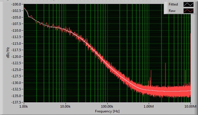
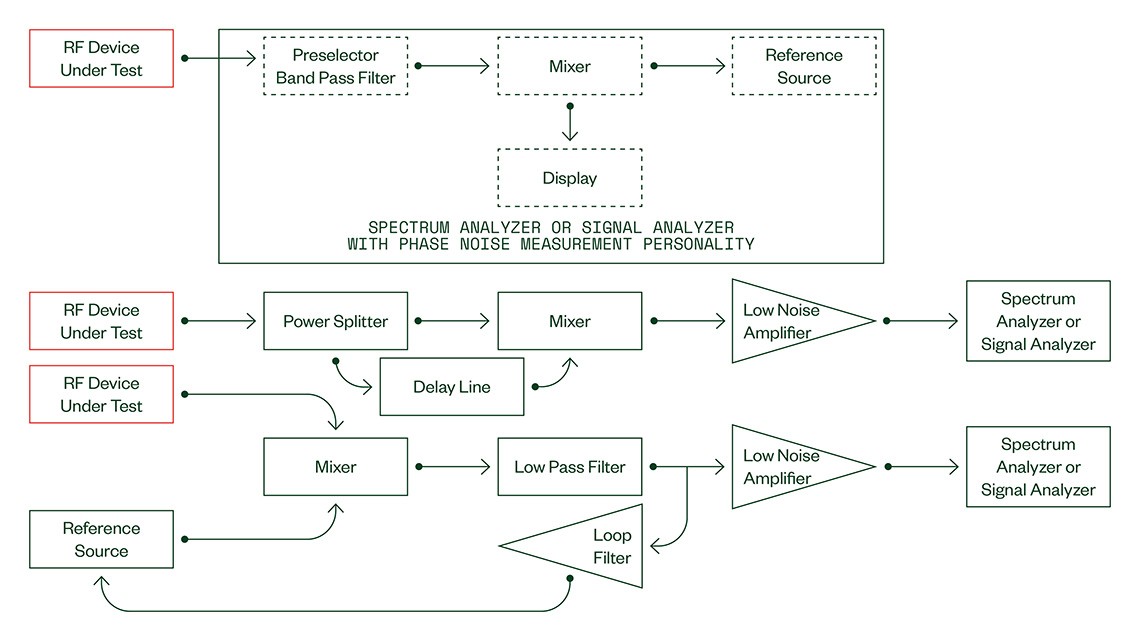
The straightforward way to measure phase noise is the direct method. With this method, a test instrument, such as a spectrum analyzer with phase noise much better than the device under test (DUT), is connected directly to the DUT, and the phase noise is plotted with a test program or internal personality. For higher performance phase noise measurements, the DUT is compared against one or more highly stable, low-phase noise sources. Two examples are the delay line method and the cross correlation method. Averaging is used to reduce the measurement noise.
Transmitter Modulation Quality
RF transmitters encode information on one or more CW carriers with modulation. Evaluating the quality of the modulated signal provides insight into the health of the entire transmitter chain from baseband to RF output. Some tests are specific to a given modulation scheme, but others are widely used. For example, with AM and FM analog modulation, modulation index and depth are generally measured.
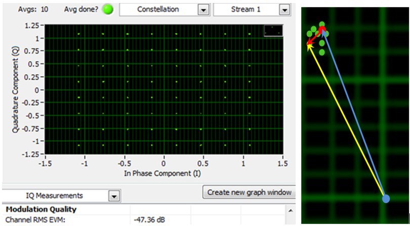
For digital IQ waveforms, error vector magnitude (EVM), also known as relative constellation error (RCE), depending on the standard being employed, describes the quality of the modulation. At each cycle of the transmitter’s internal symbol clock, the waveform’s phase and magnitude are set and transmitted. To measure the signal’s phase and magnitude accuracy, a vector signal analyzer with the appropriate IQ measurement personality is used. At each cycle of the symbol clock, the phase and magnitude values of the transmitted waveform is measured, converted to IQ components, and compared with the expected (ideal) value of the I and Q components. These ideal values, defined by the appropriate standard, are plotted on an IQ plot known as a constellation diagram. The difference between the actual value and expected value of the waveform is expressed as an error term in percent, which is the EVM. To encompass multiple IQ states, it is typically a running average of several hundred EVM measurements across the constellation diagram.
Numerous tests can be employed to analyze RF transmitters. The five tests covered in this paper are frequently used across a wide range of RF transmitters and applications. Ensuring the proper performance of an RF transmitter leads to greater accuracy, less uncertainty, higher efficiency, and reduced cost. Assessment of RF transmitters requires a methodical approach that incorporates the appropriate amount of quality testing. Care should be used with all RF components, equipment, and connections. Using the five tests herein as a foundation for a test plan leads to improved performance and reliability as well as better insight into the design and operation of an RF transmitter.


