Hean Gay Rodney Tan, UCSI University
Creating an interface control system for motor operations, from small-scale models to large industrial applications.
Developing a DC motor control system using NI LabVIEW as the main controller and processor with NI DAQ as the interface, an H-bridge as the subcontroller, and a Hall effect encoder of the motor as the sensor.
Hean Gay Rodney Tan - UCSI University
Yuen Peng Loh - UCSI University
Ying Hua Tan - UCSI University
A DC motor runs on direct current, converting electrical energy to mechanical energy in the form of rotary motion. Many applications, such as a disk drive and rotary actuator, use a DC motor. We used LabVIEW software with an NI USB-6008 DAQ module to control the rotational direction and rotating angle of a DC motor installed with a quadrature Hall effect encoder. With LabVIEW, the DC motor can have more than one operation mode. Regular DC motors can only continuously rotate in either a clockwise or counterclockwise direction, depending on the voltage polarity. We can configure a DC motor with encoders to start and stop at desired positions, which offers a wide range of application possibilities.
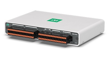
To control a DC motor, we built a system using LabVIEW as the main controller and processor with a USB-6008 DAQ module as the interface, an H-bridge as the subcontroller, and a Hall effect encoder of the motor as the sensor (see Figure 1).
We installed two Hall effect sensors 90 degrees apart in the rear shaft of the motor. These two sensors eventually produced two square wave outputs that were 90 degrees out of phase. The motor in this application had a gear ratio of 300, and the encoder produced 12 pulses per revolution, so the system produced a total of 3,600 pulse counts per main shaft revolution.
The H-bridge played an important role in controlling the rotational direction of the DC motor. As an electronic circuit, the H-bridge applied voltage across the load in both directions so that the DC motor could turn in clockwise or counterclockwise directions. We chose the integrated L293D circuit as the H-bridge for its supply voltage, current range, and output clamp diodes for inductive transient suppression.
With the Hall effect sensors and H-bridge circuit, we could use LabVIEW to freely control the DC motor to meet a variety of application needs (see Figure 2).
The two modes of control were DC motor and servo motor. In DC motor mode, the motor continuously rotated in either a clockwise or counterclockwise direction with speed display. To control the rotational direction of the motor, the system sent two digital outputs to the H-bridge through the USB-6008 DAQ module based on user selection. The user could start and stop the motor with another digital output to the pin of the H-bridge. Furthermore, the system sent encoder outputs to LabVIEW and analog inputs for the user to observe the output waveforms of the encoder and obtain the current rotational speed in revolution per minute of the motor (see figures 2 and 3).
Aside from rotational direction control, we could use the system to control the angular displacement of the DC motor (servo motor) mode. The motor shaft could displace at a set angle. As mentioned above, the encoder produced a total of 3,600 pulses per main shaft revolution. By stopping the motor after it reached a desired angle, which the system knew after the pulse count reached the desired value, the system controlled the angular displacement of the motor. The system could also calculate the pulse count of the encoder because we could configure the USB-6008 DAQ to count the rising edge or falling edge of a pulse input. By computing the number of pulses required to reach an angle and inserting the computation in the programming block diagram, the system could control the angular displacement of the DC motor (see figures 4 and 5).
By using LabVIEW as the motor controller, we can control a DC motor for multiple purposes using only one software environment. With the push of a button in LabVIEW, a DC motor can start, stop, and turn in any desired direction. In addition, we can easily adjust the position by turning a virtual knob in LabVIEW software to rotate the motor shaft to the desired angle. The system can monitor the encoder input in real time using a waveform graph in the LabVIEW front panel, which eliminates the need for an oscilloscope.
This application also uncovers the great potential of LabVIEW in robotic applications, for which continuous development provides more features to further increase the convenience of motor controls. Moreover, we can easily convert this system into other applications that require similar control sequences. LabVIEW is an open platform for easy system control in motor applications.
We used the simple graphical programming of LabVIEW for real-time monitoring of a motor’s encoder response, which saved money because the software acted as a substitute for an oscilloscope. The real-time response increased the efficiency of program testing and editing. LabVIEW proved an excellent choice for DC motor control.
Hean Gay Rodney Tan
UCSI University
Jln Menara Gading UCSI Heights South Wing Malaysia Kuala Lumpur
56000
Malaysia
Tel: 60-3-91018880-408
rodneyt@ucsi.edu.my