Main Page: Digital Instrument Cable Guide
Overview
Use this guide to better understand specifications and differences, and answer common questions, about using NI cables with your NI Digital devices and modules. This guide discusses NI naming terminology, repairing or making a custom cable, addressing noise and unexpected signals, finding information such as signal mapping and pinouts, and choosing the right cable to meet your needs—from low-cost ribbon cables to high-performance noise reducing, shielded, and more.
Contents
- Using the Digital Instrument Cable and Accessory Guides
- Understanding NI Cable Terminology
- Identifying Common NI Digital Instrument Cable Mating Connector Types and Their Pinout
- High Performance Signal Quality - Shielding and Twisted Pairs
- Troubleshooting Noise or Unexpected Readings
- Calculating Bend Radius
- NI Digital Instrument Cables Connectivity and Features
- Additional Resources
Using the Digital Instrument Cable and Accessory Guides
This guide is intended to cover cables designed for use with NI Digital Instruments including NI Digital Waveform Instruments (High-Speed Digital I/O), NI Digital Pattern Instruments, and NI High-Speed Serial devices, and their use cases. It does not cover use with other NI product families such as Switches, DAQ, C Series, or R Series, although some may use similar or the same cables. It also does not cover legacy or End of Life (EOL) NI HSDIO cables.
If you seek information about a specific cable, NI recommends that you first review this page and its more general information to better understand the product offerings, and then jump to the page for your specific model.
- To find more detailed information about your Digital Instrument cable pinout and mappings, color codes, wire gauge, dimensional drawings, mating connector, shielding and more, visit the linked cable guides in NI Digital Instrument Cables Connectivity and Features.
- To learn more about compatibility between your NI Digital Instrument accessory or cable and your NI Digital Instrument device or module, visit the Digital Instrument Cable and Accessory Compatibility Guide.
- To learn more about NI Digital Instrument accessories to use with your NI Digital Instrument device or cable, visit the Digital Instrument Accessory Guide.
- To create your own cable or test fixture, or to repair an existing NI Digital Instrument cable or accessory, visit the Digital Instrument Custom Cables, Replacement Connectors and Screws Guide.
Understanding NI Cable Terminology
NI cables come in a variety of options and functionality. This section briefly explains what some of those acronyms and other terminology means. To learn more about a specific cable, visit the Digital Cable Guide Page for your cable, or its product page.
Anatomy of a Model Name
Use this section to better understand your NI accessory's model name and numbering.
Model Prefixes
-
- SH - Shielded cables. Shielding can include individually shielded pairs and/or shielding for the entire cable assembly. See your Cable Guide for more details.
- C - Cables with a "compact" 0.8 mm VHDCI connector.
- B - Cables with an InfiniBand connector.
- H - Cables with a flying lead connector.
- No Prefix - Unshielded cables with a SCSI 0.050 D-Type connector.
Connector Identifier
Most cable models will include two numbers, the numbers indicate different values based on the cable prefix.
-
- C - Numbers indicate the pin count of the connector on each end.
- First Number- Connector found on the device end of the cable. Common Digital connectors are 68-, or 68-pin connectors .
- Second Number- Connector found on the accessory end of the the cable. Common Digital connectors are -68 and 68-pin connectors.
- B - Numbers indicate the number of lanes in the connector.
- First Number- Lanes in the connector found on the device end of the cable.
- Second Number- Lanes on the connector found on the accessory end of the cable.
- H - Numbers indicate the quantity and type of header.
- Example: H1x38 indicates 38 single position headers.
- Example: H3x24 indicates 24 three position headers.
- C - Numbers indicate the pin count of the connector on each end.
Suffix
- -D - Wire pairings designed specifically for digital applications.
Identifying Common NI Digital Instrument Cable Mating Connector Types and Their Pinout
Use this section to help identify the connector type found on your cable. To create a custom cable or for more information on replacement connectors, jackscrews or jacksockets for your NI Digital Instrument cable, use the information found throughout this guide, as well as NI Digital Instrument Device Custom Cables, Replacement Connectors, and Screws, which includes part numbers. You can also use this pinout or mapping information when creating a customer breakout fixture or terminal block.
VHDCI
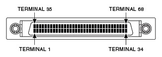
An improvement on a SCSI connector allowing a smaller footprint and fewer bent pins during connection. Features 0.8 mm pin spacing. Typically found on the device or module end. Most VHDCI cable models begin with SHC or RC ("C" indicating compact). Note: Many cables feature a SCSI 0.050 D-Type on the accessory end.
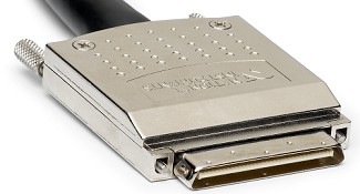 |
 |
| 68-Position Cable Connector Plug (Male) |
SCSI 0.050 D-Type
Industry standard SCSI connector standard featuring 0.050 pin spacing. Found on the device or module end or the accessory end. Most SCSI cable models begin with SH or R.
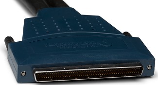 | 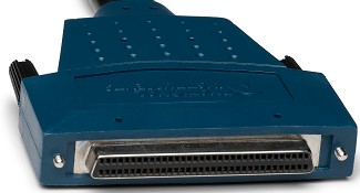 |
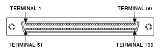 |  |
| 100-Position Cable Connector Plug (Male) | 68-Position Cable Connector Receptacle (Female) |
Infiniband
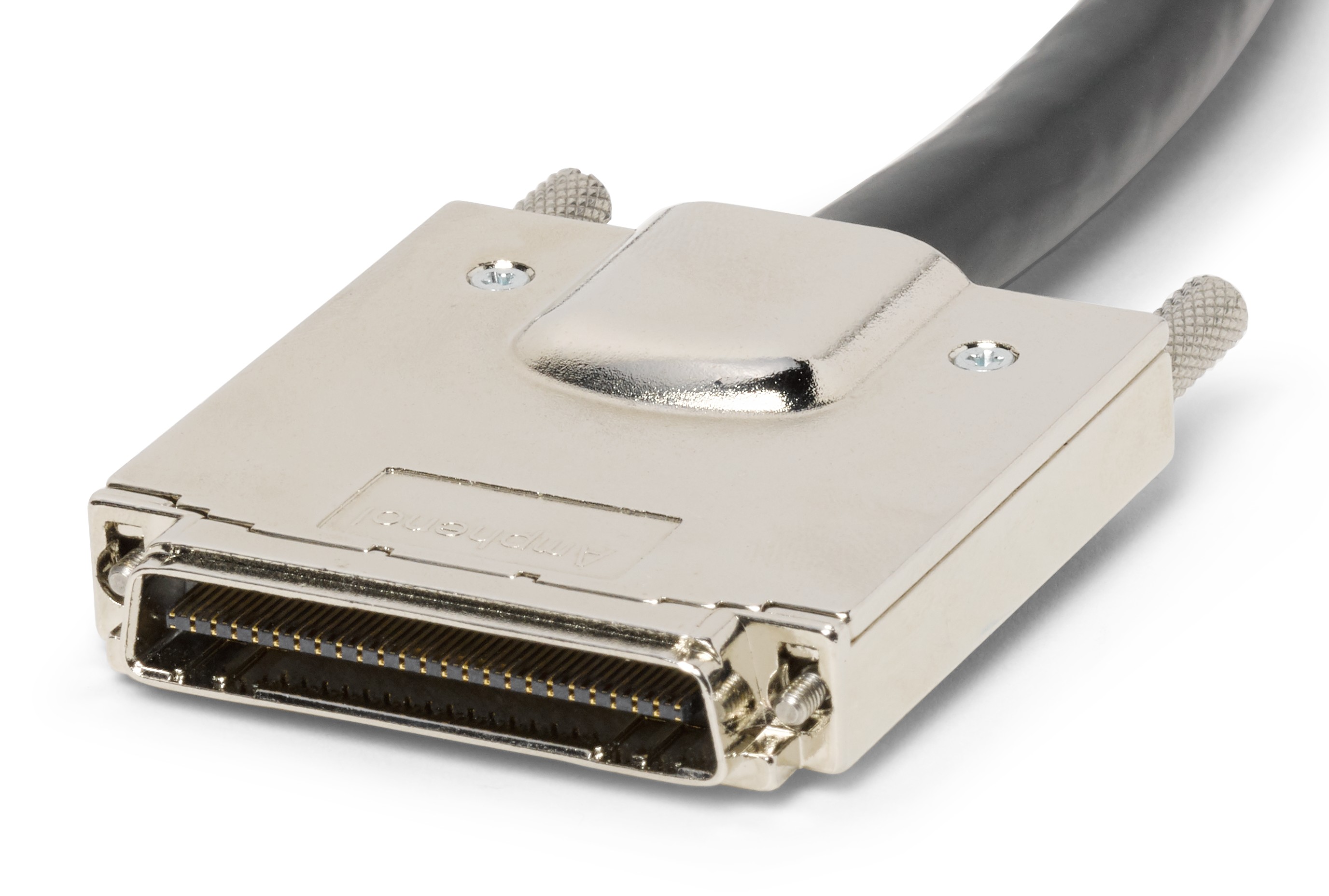
High density differential connector. Each differential pair in this cable is separated by a grounding pin to prevent cross-talk.. InfiniBand cable models begin with B.
 |
 |
| InfiniBand Connector Plug (Female) |
High Performance Signal Quality - Shielding and Twisted Pairs
NI offers an array of NI Digital Instrument cable options to meet the needs of your application. From a basic unshielded cable up to cables, such as SHC68-C68-D4 Cable, featuring specifically designed shielding and mini-coaxial cables to deliver the optimal performance. This section explains two important features that greatly affect signal quality, shielding and twisted pairs, and why you should care about them.
Shielding
Shielded cable assemblies are designed and manufactured to provide maximum performance and noise immunity. This thin layer of metallic shielding reduces electromagnetic interference from other signals on the cable, and also from external noise sources. To achieve this, the entire cable, and sometimes groupings of conductors, are enclosed in shielding
NI also sells unshielded cables for low-cost applications or for environments and applications where noise and crosstalk are not a concern.
Twisted Pairs
Some twisted pairs are optimized for signals through the use of positive (+) and negative (-) signal pairs.Other pairs may be twisted with a ground wire or drain wire. By adding twisted pairs electromagnetic interference, noise, and crosstalk can be reduced.
Shielding with Twisted Pairs
Many NI shielded cable assemblies also feature twisted pairs for improved noise performance. Different shielded cables are recommended for different devices and applications, based on signal pairings and groupings, to give the best performance.
Troubleshooting Noise or Unexpected Readings
Are you having trouble getting a good reading or is your system not working as expected? Experiencing noise, interference, unexpected or unwanted readings can originate from many parts of your system. Choosing the proper cable, and ensuring you follow best wiring practices, will help ensure the best reading.
- Choosing the correct Digital Instrument cable for your application is very important. For any environment susceptible to external noise and interference, NI recommends the use of a shielded cable. Signal integrity from both external interference and internal to the cable can also be affected by the specific wiring pairings and groupings. While many NI cables share the same connectors and pin mappings, internally the cables may be laid out very differently. NI has carefully chosen cable recommendations for each device or module based on expected signals to be carried on each line.
- Ensure that your device or module, cable, and accessory do not have any bent pins and that the cable is fully seated and secured using the jackscrews or latches. Models featuring SCSI 0.050 D-Type connectors are most susceptible to bent pins, while VHDCI and D-Sub are designed for more frequent plugging and unplugging.
- Properly grounding your signal is critical to signal integrity. Failure to ground your signal will lead to erratic or inaccurate readings.
Calculating Bend Radius
When mounting in a rack or enclosure or otherwise routing your cable , it is important to know how much you can bend the cable without damaging it. NI follows 2014 NEC Section 300.34 Conductor Bend Radius and 300.24 Bending Radius standards to define the bend radius. Per these standards, the bend radius for multi-conductor cables with individually shielded conductors is defined as 7 times the cable diameter. Cable diameter is specified in the dimensional drawings for the cable, and is also listed on the cable guide page for your cable. Use the major diameter specification for the calculation. Please refer to the dimensional drawings for the cable when calculating the bend radius. Note that some cables have additional shielding near the connectors, as a result the bend radius near the cable ends may be larger than the overall bend radius of the cable.
NI Digital Instrument Cables Connectivity and Features
The following table lists the most popular NI Digital cables, and provides links to their Cable Guide page, if available. Use this table as a starting point when selecting or picking cable options for your application. General compatibility with NI Digital devices, modules, and cables are listed on each Cable Guide page, but a more extensive list can be found in the Digital Instrument Compatibility Guide.
| Shielding | Features | Model | Device Connector | Accessory Connector | Cable Guide | Dimensional Drawing |
|---|---|---|---|---|---|---|
| Shielded | Noise reducing, high performance | SHC68-C68-D4 Cable | VHDCI | VHDCI | Link | Link |
| SHB12X-B12X | InfiniBand | InfiniBand | Link | Link | ||
| Basic shielding | SH68-68-D1 | SCSI | SCSI | Link | Link | |
| Custom connectivity, not terminated | SHC68-H1X38 | VHDCI | - | Link | - | |
| SHB12X-H3X24 | InfiniBand | - | Link | - | ||
| Unshielded | Low Cost | C68-C68-D4 Cable | VHDCI | VHDCI | Link | Link |
Additional Resources
- Learn about the compatibility of NI Digital devices and modules with NI Digital cables and accessories
- Learn about Popular Digital Instruments Accessories
- Find the parts needed to make a custom cable, breakout fixture, or replace connectors and screws on NI Digital hardware
- Browse dimensional drawings for NI cables and accessories
- Learn about DAQ Multifunction I/O Accessories
- Right Angle VHDCI Connectors P/N 778914-01 and P/N 780390-01 Replacement Notice