RF Power
- Updated2024-01-05
- 2 minute(s) read
RF Power
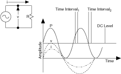
In basic electrical theory, power is calculated as the product of voltage (v) and current (i). However, in an AC circuit, the product of v and i continuously varies across time. The following figure shows an example of a sine wave generator and the resulting current, voltage, and power over time.

Notice that in this figure, the P curve varies by twice the frequency (2f) as the generated voltage. You can also observe a DC component of the power. Most RF power measurements refer to quantifying that DC term.
Average Power
In the preceding figure, you can observe that you would get a different result if you averaged the power of the signal over Time Interval1 as opposed to Time Interval2. Therefore, for AC signals, you must ensure that you average an integer number of AC periods. The average power for an AC sine wave is shown in the following formula.
where
phi (Φ) is the angle between the voltage and current waveforms.

For a modulated signal such as amplitude modulation, the power must be averaged over many periods of the modulation component.
Pulse Power
When referring to pulse power, the power is averaged over the pulse width, τ, as shown in the following equation.

The pulse width, τ, is usually taken to be the 50% rise/fall time amplitude points. Pulse power averages out such deviations as overshoot and ringing. If the pulse is rectangular, the equation simplifies to total power multiplied by the fractional duty cycle.
RMS Power
RMS power is another common notation that describes power. The RMS power notation simplifies power calculations when sinusoidal signals are involved. Finding the RMS voltage involves taking the square root of the mean value of the square of the voltage function. Thus, the procedure is described as finding the root-mean-square value of the function. The RMS value of a sinusoidal with V volts is V/0.707. After you know the RMS voltage, you can calculate the RMS power using the equation P = Vrms2/R.
Peak Power
Peak power is the largest power value in a signal. Power mismatch, the device under test (DUT) power level, device frequency, and the test environment and equipment can alter the peak power level.