Creating a Multi-VST System
- Updated2024-09-20
- 3 minute(s) read
Creating a Multi-VST System
Use the NI-RFSA and NI-RFSG drivers to configure a Multi-Channel Phase-Coherent system with NI VST.
Configuring a PXIe-5842 Multi-VST System
You can create a multi-VST system with the PXIe-5842.
- Multiple PXIe-5842 devices
- A PXIe-5655 device
- SMA power splitter x2Note The splitter size depends on the number of VSTs in the system.
Connect the PXIe-5655 LO OUT for RF IN and RF OUT to a splitter that distributes to the LO IN of each PXIe-5842 device in the system. The LO distribution through the splitters must have a loss between 0 dB and 9 dB for the frequency range of 1500 MHz to 7200 MHz.
For clock cables, attach the REF OUT connector of the primary PXIe-5842 directly into the REF IN connector of the downstream PXIe-5842. Repeat this action for each remaining VST.
For an example of an x2 system using this configuration, refer to the following cabling diagram.

Configuring the Multi-VST System
Software
After physically connecting the multi-VST system, you must programmatically configure and calibrate the system.
Use NI Hardware Configuration Utility to associate the PXIe-5655 with each connected VST. For more information on using this product, refer to the NI Hardware Configuration Utility User Manual.
- C:\Program Files\NI\LVAddons\rfsg\1\examples\instr\niRFSG\RFSG Synchronization (NI 5842 Multi-VST Configuration).vi
- C:\Program Files\NI\LVAddons\nirfsa\1\examples\instr\niRFSA\RFSA Synchronization (NI 5842 Multi-VST Configuration).vi
- C:\Program Files\NI\LVAddons\vstcalapi\1\instr.lib\niVST\Calibration\ExternalCal\Public\5842\NI 5842 Multi-VST Configuration Self Cal.vi
Specifying the
Clocking Configuration
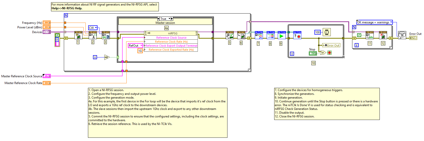
To run the devices in this configuration, set the reference clock so that all downstream devices have the correct clock. On the master session, where the PXIe-5842 receives its reference clock from the PXIe-5655, complete the following tasks:
- Set the PXIe-5655 reference clock source and rate.
- Connect the reference clock export to the RefOut output.
- Set the reference clock export rate to 1 GHz.
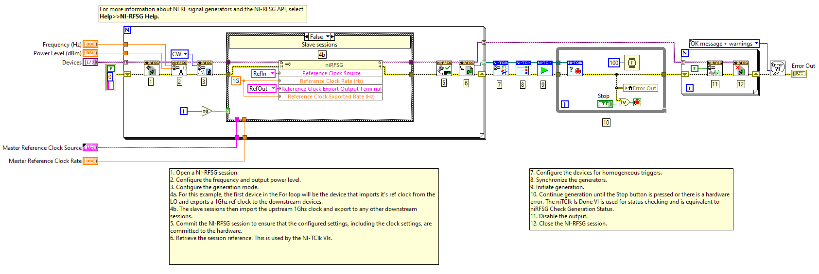
In the slave sessions, where the PXIe-5842 is downstream of the master session, complete the following tasks:
- Set the reference clock source to RefIn input.
- Set the reference clock rate to 1 GHz.
- For other downstream devices, ensure the slave session is exporting its ref clock to RefOut at 1 GHz. The PXIe-5842 will only accept a 1 GHz reference clock rate.
Self-Calibrating the
Multi-VST System
To run a system self-calibration to account for power loss, use the Multi VST Self Cal.vi.
This VI will self-calibrate each VST and reconfigure the output power of the LO to overcome the splitter loss. This calibration data is then set on the device and will persist until a regular self-calibration session is run.
Common Multi-VST Issues
Multi-VST systems may experience certain issues.
The following table displays likely problems and solutions.
| Problem | Solution |
|---|---|
|
The device loses the upstream reference clock and causes the PLL to unlock. |
Use NI Hardware Configuration Utility to reset the device and any other downstream devices. Note As a best practice, leave the 1 GHz ref clock exporting at all
times.
|
|
An IFIFO timeout error occurs during a RFSA or RFSG reset. |
The device clock was disconnected. To resolve the issue, restart the controller. |