Overview of MAC Layer Features in the LabVIEW Communications 802.11 Application Framework
Overview
Contents
- Introduction
- 802.11 MAC
- MAC Features in LabVIEW Communications 802.11 Application Framework
- Conclusions
- Additional Resources
- Bibliography
Introduction
IEEE 802.11 wireless local area network (WLAN) standard in the 2.4 GHz and 5 GHz bands is one of the most ubiquitous wireless communication standards in use. The growth in usage comes with an increase in performance requirements. To keep up with these requirements, several physical (PHY) layer and medium-access-control (MAC) layer feature enhancements have been added to the standard in the past (802.11n, 802.11ac) [1], and significant updates (802.11ax) [2] are coming soon. The standard is also facing new challenges since the cellular ecosystem is developing technologies such as LTE unlicensed (LTE-U), licensed assisted access (LAA), and MulteFire [3] to leverage unlicensed frequencies in the spectrum.
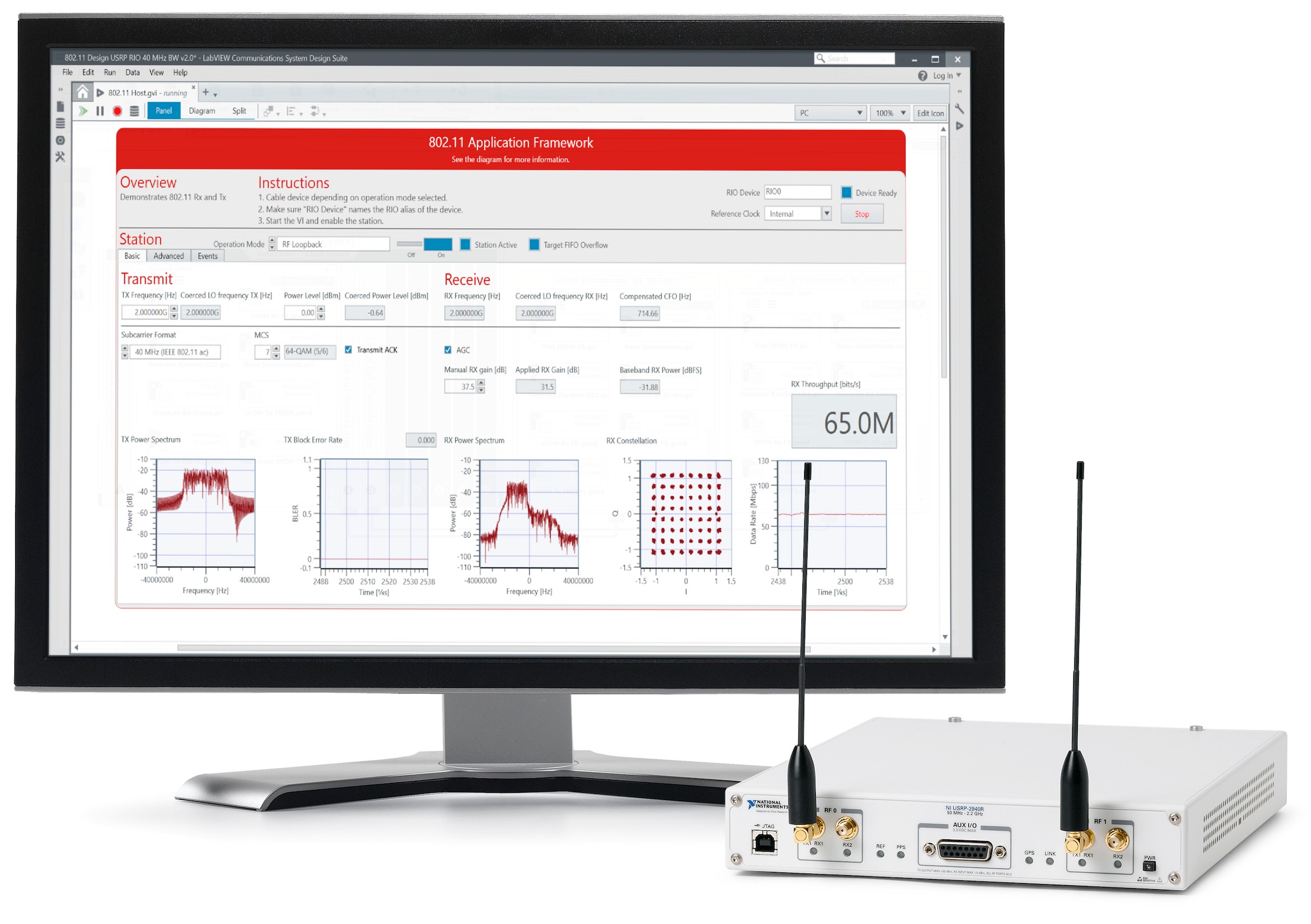
The LabVIEW Communications 802.11 Application Framework built in LabVIEW Communications System Design Suite is an FPGA based MAC and PHY layer reference design based upon the 802.11a/ac standards. When combined with NI SDR hardware as shown below in Figure 1, the 802.11 Application Framework enables researchers and engineers to develop real-time prototypes for the implementation and evaluation of innovative MAC and PHY algorithms under real world conditions. This document provides an overview of the features in the 802.11 Application Framework and should be read in conjunction with the 802.11 Application Framework white paper which provides an in-depth overview of the framework’s system architecture and includes details of the standards-compliant orthogonal frequency-division multiplexing (OFDM) PHY implementation and more.
Note that the content of this application note applies only to version 2.0.1 of the 802.11 Application Framework. More information on the product is available here.
Figure 1. The 802.11 Application Framework and NI USRP RIO.
802.11 MAC
Multiple uncoordinated devices, networks, and technologies such as 802.11, LTE-U, Bluetooth, and so on, may be present in the unlicensed spectrum. The 802.11 MAC enables fair sharing under the diverse circumstances that can be encountered in its operating band. A simple, distributed sharing mechanism called carrier sense multiple access (CSMA) forms the basis for the distributed coordinated function (DCF) MAC technique. Note that there are other MAC techniques and enhancements specified in the 802.11 standard such as point coordination function (PCF) and hybrid coordination function (HCF). The features provided by the 802.11 Application Framework can also be used to implement PCF and HCF. This application note will focus on DCF MAC, which has proven to be the most popular technique. More detailed descriptions of the 802.11 MAC are available [1], [7] (clause 10).
802.11 DCF MAC
The rest of this section provides a summary of key features of 802.11 DCF. The MAC is a packetized system where each MAC packet contains a header providing sufficient information such as packet type, source/destination MAC address, and so on, to the recipient MAC to interpret. Each MAC packet also contains a frame check sequence (FCS) based on cyclic redundancy check (CRC) to verify that the packet was correctly received. On receipt of a valid packet, the recipient sends an acknowledgement (ACK) packet. Since fast feedback of packet status enhances fair sharing of the medium, the ACK packet must be sent within a very short time period after the reception of the data packet. This time interval is called short inter-frame space (SIFS) as shown in Figure 2. If the ACK is not received, the packet transmission is assumed to have failed.
Figure 2. DATA-ACK Exchange Timing for 5 GHz OFDM PHY
The primary channel access mechanism of CSMA involves
- Listen Before Talk (LBT)
- Contention-based exponential back-off
Before sending a packet, the device conducts a clear channel assessment (CCA), that is, it senses the channel activity and defers transmission for a time interval called DCF inter-frame space (DIFS). If the channel is sensed to be free, the device can transmit immediately. Otherwise, it initiates the distributed contention process of CSMA.
The contention process is based on the following two parameters: contention window (CW) and slot period. Each device picks a random number uniformly within the interval [0, CW] as its back-off value.

The back-off countdown is initiated when the channel is sensed to be free for DIFS after a busy period as shown in Figure 3. Each contending device then proceeds to count down the back-off value for each slot period sensed to be free and starts transmitting when its count hits zero. The countdown is paused if the medium is detected to be busy during a slot. The randomness in the back-off value selection enforces a level of fairness in channel access without requiring central control.
Figure 3. CSMA Example for an 802.11 Node with Back-off = N Slots
If there is a packet error, for example, if the ACK was not received, the CW is updated by incrementing n, resulting in exponential back-off until the maximum value is reached. If there are multiple failures, the packet may be discarded due to the expiration of other timers in the protocol stack. This enables graceful fall-off in channel access under heavily loaded conditions.
Table 1 lists the values of some of the DCF MAC timing parameters. The values imply strict timing requirements; thus, an FPGA-based implementation is needed for some MAC blocks.
| DCF MAC Parameter | Value |
| SIFS | 16 µs |
| Slot Time | 9 µs |
| DIFS = SIFS + (2 x Slot Time) | 34 µs |
| CW | 2n – 1; n = 4 to 31 |
Table 1: DCF MAC Timing Parameters of 5 GHz OFDM PHY
The parameters associated with the contention-based back-off (DIFS, CWmin, CWmax) and the update formula for CW can be modified to obtain different performance trade-offs. For example, enhanced distributed channel access (EDCA) in 802.11 [1], [7] (clause 10.22.2) provides quality of service testing (QoS) support by replacing DIFS with arbitration inter-frame spacing (AIFS) and making AIFS, CWmin, and CWmax dependent on access categories such as voice, video, best effort, and background traffic.
MAC Features in LabVIEW Communications 802.11 Application Framework
The 802.11 Application Framework provides a standard compliant 802.11a, 802.11g, and 802.11ac OFDM PHY layer thereby ensuring reliability of system measurements. The focus in the current version of the 802.11 Application Framework is to provide key infrastructure blocks in the FPGA required for MAC algorithm development. The following sections describe these features.
Protocol Layering
The MAC service data unit (MSDU) is provided by the host code as shown in Figure 4. The host can generate a random packet or connect to a user datagram protocol (UDP) source. Application traffic can be supported through UDP or natively by modifying the host code. The MSDU for transmission and the relevant PHY and MAC configuration parameters for the packet are provided to the FPGA which implements the lower MAC and PHY functionality, creating the MAC protocol data unit (MPDU) and the PHY protocol data unit (PPDU). The reverse process happens in the receiver. The received MSDU can be optionally forwarded to a UDP data sink. The lower MAC and PHY blocks in the FPGA communicate through the interface described in Section "PHY-MAC Interface".
Figure 4: Protocol Layering in LabVIEW Communications 802.11 Application Framework
PHY-MAC Interface
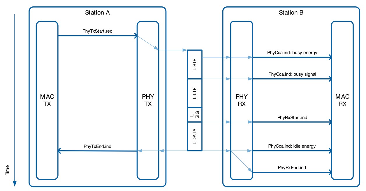
To enhance the modifiability of the Application Framework, the interface between PHY and MAC follows the physical layer service access point (PHY-SAP) interface and the concept of PHY sublayer-to-sublayer service primitives defined in the standard [4]. For the sake of simplicity, the content of those PHY service primitives is aligned with the implemented feature set. Figure 5 shows a sequence of PHY service primitives in use during a regular transmit and receive operation. In the current version of the application framework, only the following essential sublayer-to-sublayer primitives are implemented:
- PHY-TXSTART.request
- PHY-TXEND.indication
- PHY-CCA.indication
- PHY-RXSTART.indication
- PHY-RXEND.indication
Figure 5: PHY Service Primitive Sequence Chart for Typical Tx and Rx
TXVECTOR parameters
TXVECTOR represents a list of parameters that is provided by the TX-START.request. The list of parameters provided in the current framework are as follows:
- PPDU format (802.11a, 802.11ac)
- Bandwidth
- Packet length
- Modulation and coding scheme (MCS)
- TX power level
- Scrambler seed
The receiver implementation does not auto-detect PPDU format and bandwidth. Thus, these settings must be known at both nodes. The receiver can adapt to varying packet length and MCS from the appropriate header fields.
Data Transfer
The PHY-DATA.request and PHY-DATA.confirm primitives are not explicitly implemented. Instead, LabVIEW FPGA FIFO is used to transfer the MPDU between the PHY and MAC.
Early Termination
The interface does not support early termination initiated by the MAC. The primitives PHY-TXEND.request and PHY-TXEND.confirm, which are meant to provide TX early termination support, are not implemented. Instead, a PHY-TXEND.indication is provided. This primitive is used by PHY to inform the MAC that the transmission request has been processed.
Interface Error Handling
The PHY implementation in the FPGA checks that the TXVECTOR provided by the PHY-TXSTART.request primitive indicates a valid configuration. If not, the request is ignored and a PHY-TXEND.indication is sent to the MAC. Otherwise, the request is processed normally. The TX MAC implementation ensures that the data bytes for a packet is available before sending the PHY-TXSTART.request; thus, the FPGA code is not expected to produce additional error conditions during the transmission. On the RX side, similarly, the PHY implementation does consistency checks on the signaling fields before generating the RX primitives to the MAC layer.
MAC Frame Formats
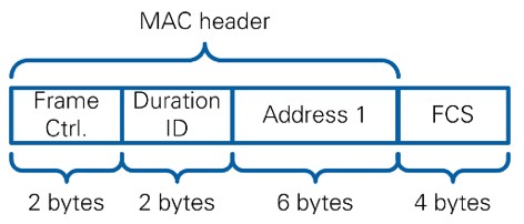
The application framework implements a compliant MAC frame and supports frame types data and ACK shown in Figure 6 and Figure 7, respectively. Hooks are provided in the FPGA code to create and recognize other frame types using the type and subtype information in the frame control field of MAC header, but the code does not process them.
Figure 6. Structure of MAC Data Frame
Figure 7. Structure of MAC ACK Frame
For data frames, the frame body carries the MSDU provided by the host code. The FCS field consists of 32-bit CRC as specified in the standard. At the receiver side, FCS check and address check are done on the FPGA, and MSDU extracted from valid data frames is provided to the host code. For debugging and logging purposes, invalid frames, such as frames with header errors or FCS errors, as well as frames directed at other users, can also be optionally forwarded to the host code from FPGA.
The following notes for the MAC header implementation in the code must be taken into account:
- In the Frame Control field (Figure 8), all bits are filled with 0 except for Type and Subtype.
- The Duration/ID field is set to 0.
- In the Sequence Control field, the Sequence Number is incremented for every packet sent. The Fragment Number is set to 0 since fragmentation is not implemented.
- HT Control and QoS Control fields are not implemented.
Figure 8: Structure of Frame Control Field in MAC Header
Support is provided in the code for users to develop these features. For example, the frame configuration cluster communicated between the modules includes a Duration/ID field, and the MAC frame header generation module packages that into the generated header.
As specified by the standard, all 802.11ac packets use aggregate MPDU (A-MPDU) format. However, support in this version is limited to A-MPDUs that consists of a single MPDU. Aggregation and fragmentation of MSDU are not supported. For fragmentation of MSDU, a simple extension of the host code can be created, and the Fragment Number field must be populated.
MAC Addresses
Address 1 and Address 2 fields in the MAC frame are utilized for destination and source MAC address, respectively. The destination MAC address is user-configurable from the host and can be programmatically changed on a per packet basis.
Address 3 and Address 4 fields are not used. By default, the Address 3 field is set to 0, and the data frame is sent using “To DS” and “From DS” subfields in the Frame Control field (Figure 8) when the MAC header is set to 0. This means that Address 4 field in the MAC header is not present in the transmitted MAC frame. Sufficient hooks are provided in the transmitter and receiver FPGA code to enable modifications that need these fields. For example, the receiver checks the “To DS” and “From DS” fields to ensure that it correctly processes packets with or without Address 4.
MAC Timing
An FPGA-based timing infrastructure is used to meet the accuracy required by the timing specifications of the MAC. The timing parameters Slot Time, DIFS, SIFS and extended inter-frame space (EIFS) are provided. A global timestamp is used to track and schedule events. Time-stamped events on the FPGA are also passed to the host for debugging and logging purposes.
DATA-ACK Exchange
If a node receives a data frame with a valid FCS and with matching destination address, it responds to the source address with an ACK. The 802.11 Application Framework meets the SIFS requirement (Figure 2). The SIFS timing generated by the MAC timing module on the FPGA is calibrated for any delay through the up conversion, down conversion, RF paths, and so on. More details are provided in the 802.11 Application Framework white paper [6]. The ACK transmission can be optionally disabled.
Clear Channel Assessment (CCA)
Energy detection-based (ED) and signal detection-based (SD) physical carrier sensing mechanisms are implemented in the PHY. CCA-ED is useful in detecting non-802.11 traffic and has a user configurable threshold. CCA-SD is 802.11 specific and depends on the fact that all 802.11 packets start with the same preamble. The PHY provides a CCA indication cluster to the MAC containing the status of energy detection and signal detection, which is used by the DCF MAC for its operation. The functionality provided by the PHY CCA can also be utilized to implement other LBT protocols and more general channel sensing based adaptation techniques (for example, LTE-U) [3].
Virtual Carrier Sensing
Virtual carrier sensing mechanisms such as network allocation vector (NAV) and RTS-CTS exchange are not implemented. The DATA-ACK exchange can be used as a template to develop RTS-CTS exchange if you require this feature.
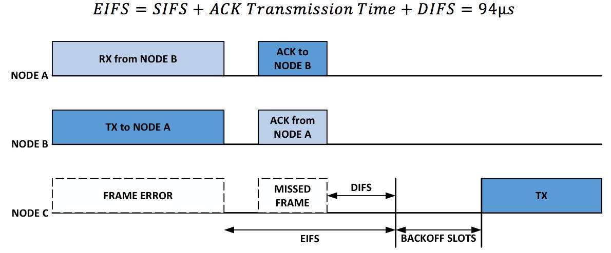
EIFS is implemented, and the packet will defer using this period, if a frame is detected but not correctly received (for example, MAC FCS failure). The EIFS is defined by the following equation. It is demonstrated in Figure 9 where the transmission from Node A cannot reach Node C, but Node B and C can reach each other. This leads to a hidden node scenario, and the use of EIFS enables the ACK from Node A to avoid potential collision due to a transmission from Node C.
Figure 9. EIFS used by Node C
CSMA
The carrier sense functionality required by CSMA is implemented as described in Section "Clear Channel Assessment". The MAC timing module provides support deferring for DIFS deferring and the slot timing required to count back-off. A back-off value can be sent along with each transmission request forwarded to the lower MAC layer in the FPGA. This value is loaded into a back-off counter which counts down as described in Section 2.1 "802.11 DCF MAC". In the application framework, the back-off value is set as constant from the host; thus, each transmission request uses this value. Variable back-off can be supported by adding an extension to the FPGA code to modify the back-off value in the transmission request.
One key feature not implemented in this version is re-transmission. To extend the application framework to support re-transmission, store the generated MPDU on the FPGA using Block RAM or DRAM and access the MPDU from this memory location if the ACK is not received within the expected time period.
Per-Packet Automatic Gain Control (AGC)
This is, strictly speaking, a PHY feature, but it is mentioned here since it is an important one for optimal operation in multi-node multiple access environment. As expected by the 802.11 specifications, the AGC level at the receiver is set for each received frame independent of other frames using the PHY training fields present at the beginning of each PHY frame. The settling time is fast enough that the signal detection and other operations can complete successfully.
Conclusions
The 802.11 Application Framework provides a unique implementation for research, development, and prototyping engineers in industry and academia. It provides a modular FPGA design with well-documented source code designed to prioritize modifiability and ease-of-understanding. This application note provides a high-level overview of the 802.11 DCF MAC features implemented in the application framework and how the application framework functions as a excellent starting point for MAC research. For more in-depth details of the reference design, please refer to the 802.11 Application Framework white paper.
Additional Resources
Visit the following websites to learn more about NI solutions for prototyping 802.11 systems.
- Software Evaluation – Download and evaluate the 802.11 Application Framework
Bibliography


