Main Page: Digital Instrument Accessory Guide
Overview
Use this guide to better understand specifications, differences, and answer common questions about using your NI Digital Instrument, including NI Digital Waveform Instruments (High-Speed Digital I/O), NI Digital Pattern Instruments, and NI High-Speed Serial, terminal block or connector block accessories as signal breakouts. You will be guided through NI naming terminology, wiring considerations, signal mapping and pinouts, choosing the right accessory to meet your needs from low cost to high-performance noise reducing, shielded, and more.
Contents
- Using the Digital Instrument Cable and Accessory Guides
- Understanding NI Accessory Terminology
- Common Cable Connector Types Found on NI Accessories
- Signal to Pin Mapping When Wiring Up an Accessory
- NI HSDIO Accessories Connectivity and Features
- Additional Resources
Using the Digital Instrument Cable and Accessory Guides
This guide is intended to cover accessories designed for use with NI Digital devices, and their use cases. It does not cover use with other NI product families such as Switches, DAQ, C Series, or R Series, although some may use similar or the same accessories. It also does not cover legacy or End of Life (EOL) NI HSDIO accessories.
If you seek information about a specific connector block or terminal block, NI recommends that you first review this page and its more general information to better understand the product offerings, and then jump to the page for your specific model.
- To find more detailed information about your High-Speed Digital I/O accessory connectors, wire gauge, pinout and mappings, dimensional drawings, device modes, mounting, and dimensions, visit the linked accessory guides in NI Digital Accessories Connectivity and Features.
- To learn more about compatibility between your NI Digital accessory or cable and your NI Digital device or module, visit the Digital Instrument Cable and Accessory Compatibility Guide.
- To create your own cable or test fixture, or to repair an existing NI HSDIO cable or accessory, visit NI HSDIO Device Custom Cables, Replacement Connectors, and Screws.
Understanding NI Accessory Terminology
NI accessories come in a variety of shapes, orientations, features, and functionality. This section briefly explains what some of that terminology means. If you want to learn more about a specific accessory, visit the NI Digital Accessory Guide Page for your accessory, or its product page.
Anatomy of a Model Name
Use this section to better understand your NI accessory's model name and numbering.
Model Prefixes
- Shielded Connector Block (SCB) - SCB accessories feature screw terminal connectivity inside of a shielded enclosure providing rugged, very low-noise signal termination. Example: SCB-68A
- Connector Block (CB) - CB unshielded screw connector blocks are low-cost accessories. These connector blocks feature standoff feet for use on a desktop or mounted in a custom breakout panel. Example: CB-68LP
- Terminal Block (TBX) - TBX unshielded screw terminal blocks are low-cost accessories that include hardware for mounting on a standard DIN rail. Example: TBX-68
Connector Pin Counts
Most SCB, CB, and TBX accessories typically follow the model prefix with a dash and a number indicating the number of pins on its connectors. Common Digital connectors are -68, and 68-pin connectors. Note that some connectors with the same pin count may come in different forms, such as the 68-pin VHDCI or SCSI.
Suffix
Following the connector pin count, some accessories also include a suffix indicating additional information or functionality. Some of the more common used are:
General Accessories Glossary
Connector Block versus Terminal Block
These terms are used interchangeably in the context of NI accessories. These accessories act as a breakout box from the pins on your NI device, featuring screw terminals connectivity when wiring signals to your system.
Shielded vs Unshielded
- Shielded - NI shielded accessories feature rugged, very low-noise signal termination. Note that NI Digital products typically must be operated with shielded cables and accessories to ensure compliance with Electromagnetic Compatibility (EMC) requirements. Example: SCB-68A
- Unshielded - NI unshielded accessories offer low-cost alternatives. They do not provide EMC shielding and thus, are more susceptible to noise interference. If unshielded cables or accessories are used, the EMC specifications for the device or module are no longer guaranteed. Example: CB-68LP
Connectivity
- Screw Terminal - A screw terminal is a type of electrical connector where a wire is held by the tightening of a screw. NI recommends one wire per screw terminal, and thus differential signals will require two screw terminals. Example: SCB-68A
- Bayonet Neill–Concelman (BNC) - Simply known in industry by its acronym, BNC is a quick connect/disconnect for coaxial cables to assist in noise reduction. In this configuration, a signal is carried down the spline (or pin) of the BNC cable, and the COM(AI-), GND or SENSE is carried down the shielding of the BNC cable. Example: BNC-2120
- SubMiniature Version A (SMA) - Similar to the coaxial cable functionality to BNC, but features a threaded barrel and hex nut for mating. Example: SMA-2164
- SubMiniature Version B (SMB) - Similar to the coaxial cable functionality to BNC, but features a smaller size and latching mechanism. Example: SMB-2163
- Deutsches Institut für Normung (DIN) Rail Mount - Simply known by its acronym, a DIN rail is an industry-standard metal rail used to mount equipment, typically inside of equipment racks. NI accessories featuring DIN rail mounts include or make available for purchase the hardware required for a simple mounting procedure. Example: TBX-68
Common Cable Connector Types Found on NI Accessories
For more information on replacement connectors for your NI HSDIO accessory, use the information found throughout this guide, as well as NI HSDIO Device Custom Cables, Replacement Connectors, and Screws.
- SCSI 0.050 D-Type (68-pin and 100-pin) - Industry standard SCSI connector standard featuring 0.050 inch pin spacing. Commonly found on Legacy NI HSDIO accessories, these accessories are compatible with older HSDIO devices and modules.. Reference compatibility information found in the Digital Instrument Cable and Accessory Compatibility for which cable to use with your device or model. Click here for a 68-pin example.
- VHDCI .8mm (68-pin) - An improvement on the SCSI connector allowing a smaller footprint with 0.8 mm pin spacing, and fewer bent pins during connection. This connector is primarily used on PXI mounted terminal blocks to connect to modules with VHDCI connectors. Click here for an example.
Signal to Pin Mapping When Wiring Up an Accessory
When wiring your sensor or other signals into your NI accessory it is important to understand which screw terminal maps back to which terminals or pin numbers on your NI Digital Waveform Instruments, High-Speed Digital I/O, NI Digital Pattern Instruments, or NI High-Speed Serial device. Even if your accessory isn't covered in the extended information pages from this guide, this guidance generally applies to mapping any NI device's lines to its accessory.
If your device has extended information available in this guide, there may also be additional information on its Digital Accessory Guide page.
First, it is important to understand that each device may use its own pinout or pin mapping scheme. Some families of devices with the same pin count will use the same numbering and signal combinations, but others may not. There are several resources you can use to find this scheme.
- User Manuals and User Guides - Depending on your model you can find your model's pinout in its user manual or user guide. Search NI Manuals to find your model's user manual or user guide.
- NI-HSDIO or Digital Pattern Help - NI Driver Help installs locally with your driver, and is also available online on ni.com/manuals . The Front Panel and Connector Pinout Help section for your device contains the pinouts for every model supported by that version of the driver.
- NI-DAQmx Help - Some Digital devices are supported by the NI-DAQmx driver. For these devices, the NI-DAQmx Device Terminals Help section contains the pinouts for every hardware model supported by that version of the driver. The NI-DAQmx Help installs locally with your driver, and is also available online.
- Measurement & Automation Explorer (MAX) - NI MAX is used to configure your NI hardware, and also references out to many different types of reference information, including device pinouts.
- Right-click your device name under Devices and Interfaces, and select Device Pinouts to directly navigate to the Help topic for your device.
- Right-click the device name under Devices and Interfaces, and select Help»Online Device Documentation. A browser window opens to ni.com/manuals with the results of a search for relevant model documentation.
- All accessories, with the exception of PXI front mounted blocks, connect to a device or module through a cable. Unless you are creating a custom breakout box or test fixture, it's typically unnecessary to understand the pin mapping at each cable and device connector. Instead, you can take the above information in regards to the signal mapping, and use that to wire to the labeled numerical screw terminals once you have connected your cable.
SCB-68 HSDIO to PXI-6541 Pinout Mapping Example
Warning: Always refer to the product documentation for your specific device. Your device may use a completely different pin mapping than what is used in this example.
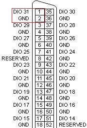
Navigate to the PXI-6541 entry in the NI-HSDIO Front Panel and Connector Pinout Help using one of the methods described above to find the following pinout diagram.
Figure 1: PXI-6541 Pinout with Pin 1 (DIO 31) and Pin 2 (GND) Highlighted
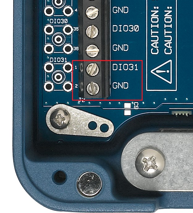
On our SCB-68 HSDIO we find terminal 1, to which we can wire our DIO31 signal wire to, and secure through the screw terminal. Similarly, we find terminal 2 to which we can wire our GND signal. In this example the pinout of the PXI-6541 aligns with the pin labels printed to the right of the screw terminals, however, this is not the case with all devices, an example of this can be found below. To ensure that you are properly wiring your device use the pin numbers on the circuit board.
Note: In the case of the SCB-68 HSDIO the pin number can be found on the opposite side of the screw terminal from the terminal name.
Figure 2: SCB-68A HSDIO with Terminals 1 and 2 Highlighted
SCB-68 HSDIO to PXIe-6535 Pinout Mapping Example
Warning: Always refer to the product documentation for your specific device. Your device may use a completely different pin mapping than what is used in this example.
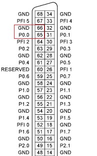
Navigate to the PXIe-6535 entry in the entry in the NI-DAQmx Device Terminals Help using one of the methods described above to find the following pinout diagram.
Figure 3: PXIe-6535 Pinout with Pin 65 (P0.0) and Pin 66 (GND) Highlighted
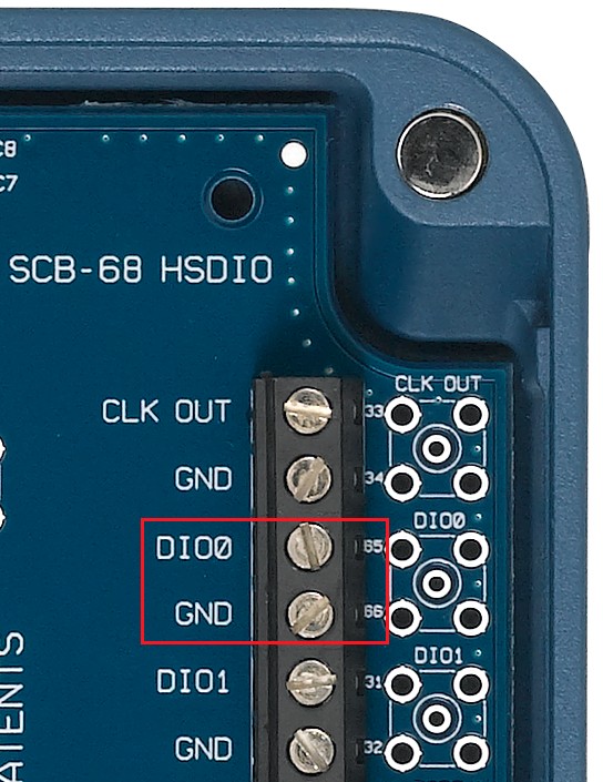
On our SCB-68 HSDIO we find terminal 65, to which we can wire our P0.0 signal wire to, and secure through the screw terminal. Similarly, we find terminal 66 to which we can wire our GND signal. In this example the terminal names of the PXIe-6535 do not align with the terminal labels printed to the right of the screw terminals. To ensure that you are properly wiring your device use the pin numbers on the circuit board.
Note: In the case of the SCB-68 HSDIO the pin number can be found on the opposite side of the screw terminal from the terminal name.
Figure 4: SCB-68A HSDIO with Terminals 65 and 66 Highlighted
NI HSDIO Accessories Connectivity and Features
The following table lists the most popular NI Digital accessories, and provides links to their Accessory Guide Page, if available. General compatibility with NI Digital devices, modules, and cables are listed on each Accessory Guide page, but a more extensive list can be found in the Digital Instrument Compatibility guide. For more information about an accessory not covered in this guide, review the accessory's manual.
| Connectivity | Shielding | Product Page | Accessory Guide | Mounting |
|---|---|---|---|---|
| Screw Terminal | Shielded for high performance noise reduction | SCB-68 HSDIO | SCB-68 HSDIO | DIN Rail2 |
| SCB-68A1 | SCB-68A | DIN Rail2 | ||
| SCB-681 | SCB-68 | - | ||
| Screw Terminal | Unshielded for low cost applications | CB-68LP | - | Custom Panel |
| CB-68LPR | - | Custom Panel | ||
| TBX-68 | - | DIN Rail | ||
| SMA | Shielded for high performance noise reduction | SMA-2164 | - | - |
| SMB | Shielded for high performance noise reduction | SMB-2163 | - | - |
| Cable Adapter VHDCI-SCSI | N/A | 653x Cable Adapter | 653x Cable Adapter | - |
1The SCB-68 and SCB-68A must be configured in Direct Feedthrough Mode. For more information on how to configure these accessories in Direct Feedthrough mode see the SCB-68 and SCB-68A Accessory guide.
2DIN rail kit sold separately.
Additional Resources
- Learn about the compatibility of NI Digital devices and modules with NI Digital cables and accessories.
- Find the parts needed to make a custom cable, breakout fixture, or replace connectors and screws on NI Digital hardware.
- Learn about cables used with NI Digital Instruments.
- Browse and search NI manuals, guides, specifications, datasheets, getting started guides, and more.
- Browse dimensional drawings for NI cables and accessories.
- Learn about DAQ Multifunction I/O Accessories.


