From Saturday, Nov 23rd 7:00 PM CST - Sunday, Nov 24th 7:45 AM CST, ni.com will undergo system upgrades that may result in temporary service interruption.
We appreciate your patience as we improve our online experience.
From Saturday, Nov 23rd 7:00 PM CST - Sunday, Nov 24th 7:45 AM CST, ni.com will undergo system upgrades that may result in temporary service interruption.
We appreciate your patience as we improve our online experience.
Data logs from VeriStand come in a variety of formats. Ranging from single point data to XNET raw frames to high speed waveform data from one or more targets. Combining and viewing the data in these logs is a challenge due to the variety of technologies and data formats. DIAdem is a powerful tool that can make this process painless. This article provides a tutorial including a time alignment DIAdem SCRIPT, example files, and step by step instructions.
To accurately view VeriStand data logs based upon time, the time information in the logs must be correctly time-correlated. Therefore as a prerequisite to this tutorial, ensure the system is synchronized with a common signal or time-based source. Visit Using Synchronization to Build Integration Test Systems with VeriStand to validate your system configuration.
NI VeriStand contains many data logging methods and formats. The most common ones are listed and discussed here.
| Name | File on Host or Target | TDMS Channel Data Type | DIAdem Plotting Style | Time Stamp Format |
|---|---|---|---|---|
| Host Side Data Logging | Host | Doubles | X / Y | Relative or Absolute values in a channel |
| Embedded Data Logger | Target | Doubles | X / Y | Relative or Absolute values in a channel |
| DAQmx Task Logging | Target | Waveform | Relative to first point starting at "X offset" property value | Absolute time property for first point. Delta T property for subsequent points |
| XNET Raw Frame Logging | Target | Raw, convert to doubles | X / Y | Absolute time property for first point. Relative values in a channel. |
| Waveform Data Logger Custom Device | Target | Waveform | Relative to first point starting at "X offset" property value | Absolute time property for first point. Delta T property for subsequent points |
This logging method is for single point channel data and is typically invoked by the stimulus profile editor or through the available LabVIEW and .NET APIs. This API is feature rich, high performance, and is the preferred method of logging channel data if it is possible to keep the host connected to the target. Time information needed for correlation is not automatically included in the log. To add time information, in addition to the channels of interest, log either the System Time system channel if you're not correlating with waveforms or XNET or the Absolute Time system channel if you are. Then the data log will contain a time stamp for each point of channel values.
When logging the Absolute Time system channel, the values are in seconds relative to 12:00 a.m., Friday, January 1, 1904, Universal Time [01-01-1904 00:00:00]
VeriStand channel values are double data type, so they are logged into the TDMS file as double channels.
This logging method is for single point channel data and is configured inside the VeriStand system definition as a custom device. The logging occurs on the target so this is ideal for situations where the host is not always present or fail safe data logging.
Time information needed for correlation is not automatically included in the log. To add time information, in addition to the channels of interest, log either the System Time system channel if you're not correlating with waveforms or XNET or the Absolute Time system channel if you are. Then the data log will contain a time stamp for each point of channel values.
When logging the Absolute Time system channel, the values are in seconds relative to 12:00 a.m., Friday, January 1, 1904, Universal Time [01-01-1904 00:00:00]
VeriStand channel values are double data type, so they are logged into the TDMS file as double channels.
This logging method is for waveform data and is configured inside the VeriStand system definition on the DAQ task. Waveforms can contain huge amounts of data, so logging occurs on target to avoid network throughput issues.
VeriStand's Tasks configure waveform acquisition, so data is logged into the TDMS file as waveform channels. Waveform channels have a property for an absolute time stamp of the first sample, t0, and a property for the time delta of subsequent points.
This logging method is for XNET raw frame data directly to disk and is configured inside the VeriStand system definition under the XNET port's incoming section. It can be configured to log incoming frame data or contain both incoming and outgoing frame data if echo is enabled on the port.
XNET devices time stamp incoming and outgoing frames, which is useful when doing data analysis on raw bus communication. For example, you can diagnose an issue with a DUT coming into and out of sleep. These time stamps are stored inside the XNET raw data logs. XNET devices use a hardware time stamping strategy to provide extremely accurate time stamps. When a frame is sent or received, it is time stamped directly at the XNET board without CPU involvement.
The data inside the resulting TDMS file is in a raw format that is unreadable until converted. DIAdem includes a converter tool that loads raw XNET TDMS files and an XNET database and then creates a converted TDM file containing easily readable double channels. Access this tool on the NAVIGATOR tab and on the left column click the bus log converter icon. Alternatively, DIAdem can be configured to automatically convert XNET raw data logs to double channels upon load. When using the same database frequently, use the automatic convert setting. Configure this setting by first creating a conversion configuration file (*.tcc) with the aforementioned tool, and then select the NAVIGATOR tab » Settings » Options » NAVIGATOR. Pick the *.tcc file and check Converting the XNET-TDMS channel when loading.
After conversion each frame contained in the raw log will have a corresponding group of signals in the converted log. This group has a Time channel that contains time stamp values for each corresponding point of signal data in the group. The time channel starts at 0. The "CANTimeStamp" property on the group provides an absolute time of the first time value, t0. Unfortunately this absolute time property value is in double format of seconds since 0 AD, which has a precision of only 0.1ms. The attached patch for NI DIAdem 2012 makes the conversion process also tag a new high precision time stamp property named "CANDateTimeStamp".
To install this patch, back up the existing dll files of the same name and then copy the attached files into:
<Program Files>\National Instruments\DIAdem 2012\
This logging method is for waveform data and is configured inside the VeriStand system definition as a custom device. Waveforms can contain huge amounts of data, so logging occurs on target to avoid network throughput issues.
VeriStand's waveform nodes are of waveform data type, so data is logged into the TDMS file as waveform channels. Waveform channels have a property for an absolute time stamp of the first sample, t0, and a property for the time delta of subsequent points.
In certain synchronization scenarios, when only logging channel data, the System Time system channel can be used as the X axis. Plotting this data is easily done by simply dragging and dropping. An entire group of double channels can be dragged onto the plot and DIAdem will use the first double channel values in the group as the X axis locations. Therefore be sure to select the time channel as the first channel to log, or adjust the group's channel ordering in DIAdem before dragging and dropping a group. When plotting a subset of a channel group, select the time channel first before dragging and dropping.
In certain synchronization scenarios, or when logging channel data with XNET raw frames or waveform data, absolute time must be used as the time reference. As noted in the table at the beginning of this article, XNET raw frames and waveform logs always contain absolute time stamps. When plotting data with absolute time, finding the relationship between data points in time is the goal. Ideally this can be done visually with a plot. With the variety of data types, plotting styles, and time formats, plotting can be a challenge.
To resolve this challenge, a technique can be used to adjust the data so it is displayed by relative time to the first point instead of by absolute time. This makes it easier to follow the data because the X axis is in seconds instead of a very detailed day of week, month, year, etc. After converting any XNET raw data logs to engineering units, apply this technique:
Time information for each channel or waveform is now relativized for simple drag and drop plotting.
This process can be automated with a DIAdem VB Script and assigned to a button and keyboard shortcut in the VIEW tab. A VB script that identifies VeriStand time channels, XNET time channels and waveforms and relativizes them is attached. This script works for the majority of use cases but could be customized if you have different needs.
Certain data acquisition devices contain Delta Sigma analog to digital converters, usually with anti aliasing filters. These devices cause time delays on the acquired data between 10-500 microseconds. The time delay is specific to the device and will be specified in the manual for that device. Often these delays are dependent on the frequency of the signal being measured and a graph will be provided in the device manual.
Unfortunately, as of DAQmx 9.8, for most devices the time stamp for the acquired data will not be compensated for this delay and it is up to the user to measure and compensate for this delay. Corrective action request #422495 is active for DAQmx to automatically adjust the waveform t0 timestamp for this delay. Until then, use a technique such as the sample scenario below where a single signal was measured by multiple devices to find this delay.
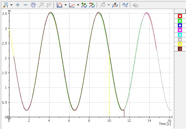
In this sample, a sine wave signal was acquired with DAQmx waveform logging, XNET raw frame logging, and channel data logging from FPGA and EtherCAT single point acquisition. The system was configured according to synchronization scenario #12 in Using Synchronization to Build Integration Test Systems with VeriStand. A diagram of the system can be seen in Figure 1.
Figure 1: NI VeriStand system used to acquire the attached sample data logs.
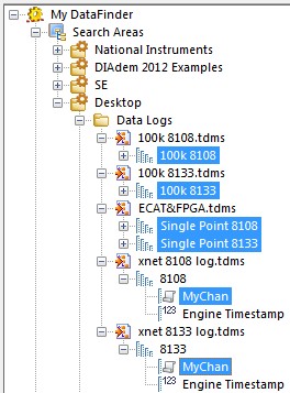
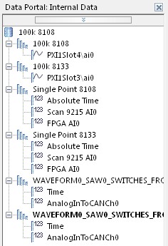
Follow these step by step instructions with the attached logs to view the data time correlated.


 )
)