Using Synchronization to Build Integration Test Systems with VeriStand
Overview
VeriStand's configuration based environment makes it possible to create a diverse system consisting of many different kinds of I/O on one or more execution targets. Proper synchronization of the diverse I/O and targets is critical for consistency, performance and data analysis.
This article discusses how to properly build and configure VeriStand systems for synchronization. This is required for integration testing applications commonly called iron birds or full vehicle simulators.
Contents
- Introduction
- Synchronization Technology
- NI VeriStand
- Synchronization Challenges
- Proving Synchronization
- Synchronization Scenario Solution Quick Reference Table
- Synchronization Scenario Solution Guide
Introduction
It is important to think about timing and synchronization requirements when designing a system. If the system is not synchronized, the sampling of inputs and outputs does not happen simultaneously. Also, drift over time can cause one component of the system to collect more samples than another even if they are configured for the same rate. This can cause problems for simulation systems. For example, one simulation model could be in a different time state than the other. Finally, data analysis can be difficult or impossible without an accurate common time base.
Synchronizing a distributed system involves hardware and software synchronization. Optionally, you can synchronize the entire system to an external time reference such as 1588, GPS or IRIG.
There are two types of synchronization. Time and signal based synchronization. Time based synchronization uses absolute "wall clock" time as a reference for events. Signal based synchronization uses physical hardware pulses as a reference for events. Some hardware uses time based synchronization, others use signal based, and some both. Depending on the exact configuration, a system may contain only one type of hardware and therefore be simpler to synchronize. However, a synchronization solution that bridges between time and signal is typically recommended to facilitate the greatest flexibility.
Synchronization Technology
Time Based
Time based synchronization means each piece of time based hardware in the system shares a common time reference. For example, two cell phones will have approximately the same time because most cell phones retrieve time information from the cell tower. Time could then be used to initiate sampling events on data acquisition and generation devices. Time based synchronization is also useful for post processing data correlation. For example: "When, relatively and absolutely, did one of my system components output value X compared to input value Y?"
For test and measurement hardware there are many industry standards for time like 1588, GPS, NTP, PPS, and IRIG. These have varying precision and connectivity medium. For example GPS requires an antenna and 1588 requires Ethernet.
Signal Based
Signal based synchronization means each piece of signal based hardware in the system shares a hardware clock for timing. This is either a directly shared sample clock between devices or a high frequency reference clock like the 10 MHz PXI chassis clock that each device can derive sample clocks from and a shared start trigger.
Examples of common signal based synchronization tasks include simultaneously sampling on several data acquisition boards, updating the PWM duty cycle on the digital output of a field-programmable gate array (FPGA) board and updating data acquisition analog outputs. Synchronization is also often needed for data coherency in live or post processed data analysis. For example, some models will not close their control or simulation loop properly if they receive data from slightly different points of time.
When multiple signal based devices are synchronized that means they will update I/O simultaneously and also drift (same number of samples over a period) together.
NI VeriStand
Terminology
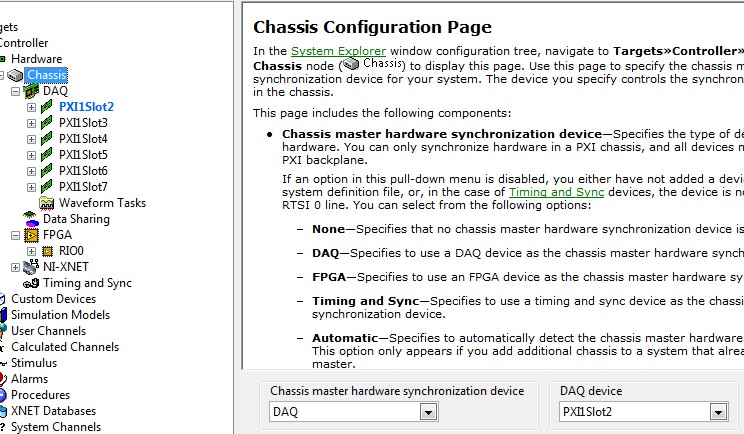
- Chassis master device - The device selected to distribute sample clocks for signal based devices in the same chassis. NI VeriStand automatically configures the chassis master device to export a sample clock throughout a PXI chassis (or RTSI cable if using PCI) to all other hardware timed single point DAQ and FPGA devices. This sample clock is routed from the chassis master using PXI_Trig0 (or RTSI0). The chassis master device is shown in bold blue in the system definition tree and, if it is a DAQ device, has some additional configuration options on the chassis page. This is typically automatically selected by NI VeriStand. See Figure 1.
Figure 1. The chassis master device is selected as DAQ and that device is shown in bold blue.
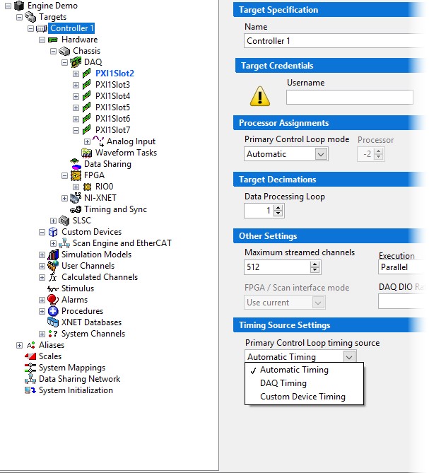
- Primary Control Loop timing source - The source selected to provide interrupts for the NI VeriStand Engine's Primary Control Loop for the start of a loop iteration. This is typically done by a hardware device when samples are acquired so the primary control loop knows to start and read the newest samples. This is automatically selected by NI VeriStand. It can be a hardware timed single point DAQ device with at least one analog input in the system definition, an FPGA device, or a custom device. See Figure 2.
Figure 2. The Primary Control Loop timing source selection on the controller page.
- System Time system channel - This system channel provides the relative system time of the NI VeriStand Engine according to the iteration count and Delta T of the Primary Control Loop
- Absolute Time system channel - This system channel provides the current date and time in seconds relative to 12:00 a.m., Friday, January 1, 1904, Universal Time [01-01-1904 00:00:00].
Common Device Types
| Device Type | Sample Type | Synchronization Type |
|---|---|---|
| Hardware timed DAQ | Single point | Signal |
| Software timed DAQ | Single point | Time |
| FPGA | Single point | Signal |
| XNET | Frame time stamp | Signal and Time |
| Scan Engine & EtherCAT | Single point | Time |
| Waveform Acquisition | Waveform | Signal and Time |
DAQ Devices
DAQ devices can be used in 3 different modes with NI VeriStand:
- Hardware Timed Single Point - Use a hardware sample clock to latch analog inputs and outputs and transfer these to/from the CPU one event at a time. The sample clock can be internally derived from the PXI chassis clock (if the device is designated as the chassis master in the system definition) or received on a digital pin (if the device is not the chassis master). Therefore, DAQ devices in this mode are signal based synchronization devices. NI VeriStand will pick a DAQ device in this mode automatically to be the primary control loop timing source, with the interrupt firing on the sample clock rising edge.
- Software Timed Single Point - No hardware sample clock is used. Samples are retrieved and outputted to/from the CPU one event at a time when software calls the appropriate read or write API.
- Waveform acquisition - Use a hardware sample clock to latch analog inputs and transfer these to the CPU in large chunks. The sample clock can be internally derived from the PXI chassis clock or received on a digital pin. When the first point of data is received by the CPU, it is time stamped with system time (t0). Therefore, DAQ devices in this mode are both time and signal based synchronization devices.
FPGA Devices
FPGA devices can be used in many different ways, but they are typically used in NI VeriStand one of these scenarios:
- Single point - The FPGA logic was developed using the NI VeriStand template and is added to the system definition under the Chassis » Hardware » FPGA. This template uses a hardware sample clock to latch inputs and outputs and transfer these to/from the CPU one event at a time. The sample clock can be internally derived from the PXI chassis clock* (if the device is designated as the chassis master in the system definition) or received on a digital pin (if the device is not the chassis master). Therefore, FPGA devices in this mode are signal based synchronization devices. NI VeriStand will pick an FPGA device in this mode automatically to be the primary control loop timing source if no hardware timed single point DAQ device is available, with the interrupt firing on the sample clock rising edge.
- From a custom device - The FPGA logic was developed specifically for use with a custom device and its content is known by the developer. There is no entry for this FPGA device in the system definition other than the custom device(s) accessing it. Custom devices interfacing with FPGAs often contain sensor simulation code. Since these are simulations free-running on the FPGA, they don't have any synchronization requirements. Other custom devices might capture waveforms from an FPGA and therefore Chassis Clock Synchronization* is needed.
- Single point and from custom device - Combining #1 and #2. The FPGA contains the NI VeriStand single point template and additional logic that will be simultaneously accessed by a custom device and NI VeriStand. There are multiple entries in the system definition, the custom device(s) and under Chassis » Hardware » FPGA. Because FPGA devices used this way are also doing #1, these devices are signal based synchronization devices.
*When using R series FPGA devices it is important to enable the PXI Chassis Clock Synchronization setting in "RIO Device Setup" in your start menu. This is by default off and can cause drift when using an FPGA device in certain configurations.
XNET Devices
PXI XNET devices read and write data from communication buses. These devices time stamp incoming and outgoing frames, which is useful when doing data analysis on raw bus communication. For example, you can diagnose an issue with a DUT coming into and out of sleep. In NI VeriStand, these time stamps are visible in the XNET raw data logs configured under each XNET port, and in the frame information channels for incoming frames.
XNET devices use a hardware time stamping strategy to provide extremely accurate time stamps. When a frame is sent or received, it is time stamped directly at the XNET board without CPU involvement. Internally, this is accomplished by a three step process:
- When an XNET session is created, system time is copied to the XNET hardware
- While the XNET session is active, the XNET hardware increments its time counter via the PXI 10 MHz chassis clock
- When a frame is sent or received, the XNET hardware uses its time counter to tag a time for that event
XNET devices use system time for t0 and then signal based synchronization for further time increments. Therefore these devices are both time and signal synchronized.
Scan Engine and EtherCAT
Scan Engine and EtherCAT single point I/O is time based and is not clocked via a physical sample clock or referenced to a chassis clock. Every device on an EtherCAT network knows the system time and samples at periodic intervals (for example, every 200uS). This is implemented into NI VeriStand with the Scan Engine and EtherCAT Custom Device. This custom device will not be automatically selected to be the Primary Control Loop timing source, but it can be explicitly selected. If selected, the I/O scan initiation interrupt is used to time the Primary Control Loop. If not selected, the I/O scan will run asynchronously, configurable with a decimation, from the Primary Control Loop.
Synchronization Challenges
Signal Based Expansion Chassis
When combining a single PXI controller in a single PXI chassis with signal based synchronization expansion chassis like MXIe RIO or a MXI PXI chassis performing single point acquisition or generation, the sample clock that is distributed from the chassis master device needs to reach all signal based single point devices or the system will suffer performance issues due to lack of synchronization. MXIe RIO chassis requires external distribution of the sample clock (see note in the NI VeriStand FPGA template document). Additional MXI PXI chassis require the sharing of chassis reference clock and start trigger.
Multiple Synchronization Types
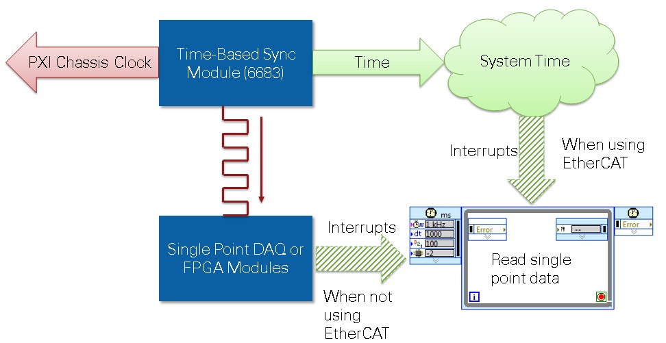
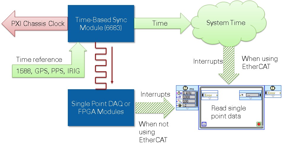
A NI VeriStand system that only contains hardware timed single point DAQ and FPGA, even if it is distributed among many chassis and CPUs is simple to synchronize because it only contains signal based devices. However, if your requirements also include analyzing XNET bus traffic time stamps in relation to IO or on different targets, using EtherCAT expansion chassis, or time correlating high speed waveform data, then you have a mixed system that must provide synchronization across both types. Accomplish this with a time based synchronization module like the PXI-6683 within a single chassis. The time based synchronization module can override the chassis reference 10 MHz clock with a time disciplined clock and directly control the system time. When using multiple controllers in multiple chassis, multiple time based synchronization modules can be connected to share time over Ethernet using 1588 or connected an external time reference like GPS, IRIG, 1588 or PPS. To use a time based synchronization module in NI VeriStand, the Chassis TimeSync Custom Device is required.
Note: The PXI-6682 is a time based synchronization module but it cannot create a disciplined 10 MHz clock to override the chassis clock and must be combined with a PXI-6653 or PXIe-6674T. Therefore a PXI-6683 or newer is recommended.
When using multiple single point devices in NI VeriStand, they should almost always* be synchronized. Otherwise there can be serious performance issues. Imagine NI VeriStand configured at 1000 Hz and the system definition contains two single point devices such as hardware timed DAQ, EtherCAT or FPGA. If the devices are not synchronized, they are not guaranteed to sample at the same time. If each device samples 180 degrees out of phase from the other, the NI VeriStand execution engine will spend 50% of its loop time waiting for the next device’s samples after it receives the firsts. Worse, as they do not stay exactly 180 degrees out of phase, the target CPU usage will float from 0% to 100% as the phase difference changes.
*Note: Software timed single point DAQ does not suffer from this synchronization based performance issue because the sampling is initiated by software read and write API calls.
Viewing Time Correlated Data Logs
Data logs from NI VeriStand come in a variety of formats. Ranging from single point channel data to XNET raw frames to high speed waveform data. Combining and viewing the data in these logs is a challenge due to the variety of technologies and data formats. DIAdem is a powerful tool that can make this process painless. See Viewing Time Correlated NI VeriStand Data Logs for a tutorial including a time alignment DIAdem SCRIPT, example files, and step by step instructions.
Proving Synchronization
Synchronization can always be proved through data logging and analysis. However, in certain scenarios, it can be proved quicker by observing the lack of synchronization related performance issues:
- When only using single point devices with a single controller, simply graph the HP Loop Duration system channel in NI VeriStand. If this value settles and does not drift over time, the single point devices are synchronized.
- When using a time based synchronization module to synchronize time between multiple controllers, time synchronization can be proved by graphing the Absolute Time system channel of each controller. The values should match.
- When using reflective memory between multiple controllers, single point synchronization between them can be proved by the lack of ring read and ring write late counts in the reflective memory status channels. These late counts only happen between unsynchronized controllers because their primary control loops are drifting in and out of phase from each other.
In all situations synchronization can be proved by acquiring a reference signal from several devices, logging the acquired values along with time information, and plotting the data on a graph:
- When only using hardware timed single point devices that are signal based (DAQ, FPGA), data logs should be collected containing the acquisition values of interest (AI0, AI1, etc) as well as System Time. System Time should then be used as the X axis values when plotting on an X / Y graph or 2D Axis System in DIAdem.
- When using time and signal based devices, acquiring a common signal and then viewing based upon absolute time is required. See Viewing Time Correlated NI VeriStand Data Logs for a tutorial including a time alignment DIAdem SCRIPT, example files, and step by step instructions.
In the following list of scenarios, the proving technique for each is listed.
Synchronization Scenario Solution Quick Reference Table
| Scenario | HWTSP DAQ or FPGA | Waveform Acquisition Without Time Drift | XNET Time Without Drift | EtherCAT | Controllers | Chassis |
|---|---|---|---|---|---|---|
| #1 | Yes | No | No | No | 1 | 1 |
| #2 | Yes | No | No | No | 1 | 2+ |
| #2 | Yes | No | No | No | 2+ | 2+ |
| #3 | MXIe RIO Example | No | No | No | 1 | 1 |
| #4 | Yes | Yes | Yes | No | 1 | 1 |
| #5 | Yes | Yes | Yes | No | 1 | 2+ |
| #6 | Yes | Yes | Yes | No | 2+ | 2+ |
| #7 | No | No | No | Yes | 1 | 1 |
| #8 | No | Yes | Yes | Yes | 1 | 1 |
| #9 | No | Yes | Yes | Yes | 2+ | 2+ |
| #10 | Yes | Yes | Yes | Yes | 1 | 1 |
| #11 | Yes | Yes | Yes | Yes | 1 | 2+ |
| #12 | Yes | Yes | Yes | Yes | 2+ | 2+ |
Synchronization Scenario Solution Guide
In this section several system scenarios will be presented and the proper hardware and software solution to synchronize the system will be indicated. Visit the scenario that applies for your system.
#1. Hardware Timed Single Point DAQ and FPGA, Single Chassis
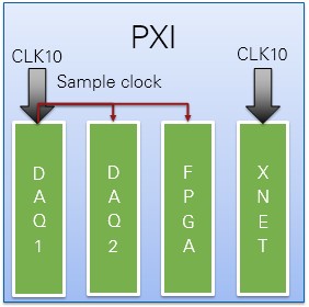
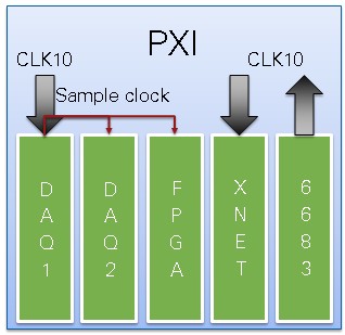
XNET could be used, but in this scenario, the user is not concerned with the time stamping of XNET frames on the bus. Therefore all devices are signal based synchronization single point devices. NI VeriStand's automatic configuration will handle this case without user intervention. See Figure 5.
The CPU could be inside the PXI chassis or from a separate PC like a desktop or rack mount computer and connected via MXI.
Waveform acquisition could be used but in this scenario the user is either not concerned with waveform acquisition or is not concerned with the time stamps in their waveform data logs.
When viewing data logs, time correlation is accomplished via logging channel data values along with the System Time channel and displaying in in X / Y format.
Synchronization of single point devices can be proved by graphing the HP Loop Duration system channel in NI VeriStand. If this value settles and does not drift over time, the single point devices are synchronized.
Figure 5. DAQ1 is chassis master and exports a sample clock through the chassis to DAQ2 and FPGA.
#2. Hardware Timed Single Point DAQ and FPGA, Multiple Chassis
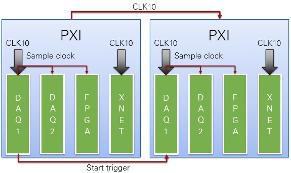
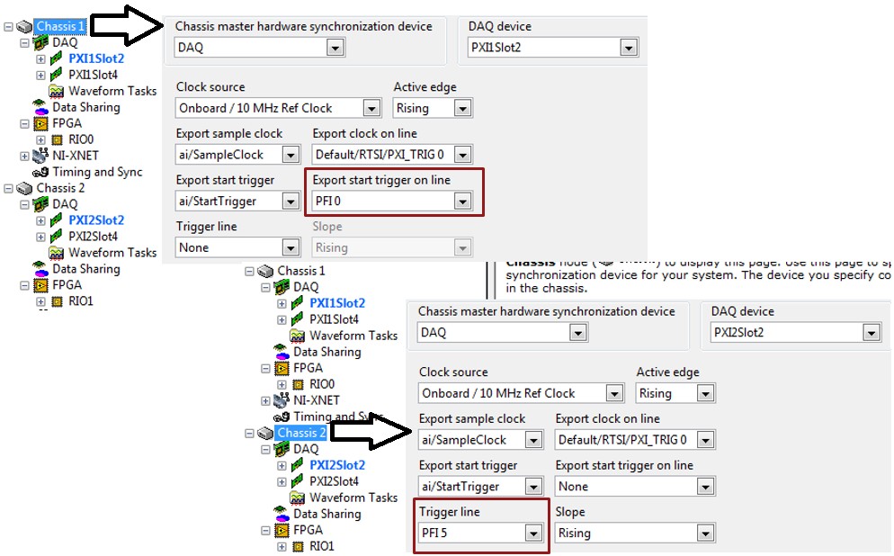
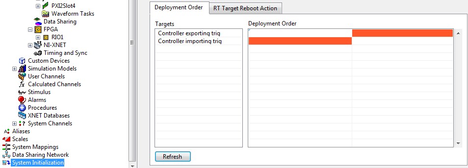
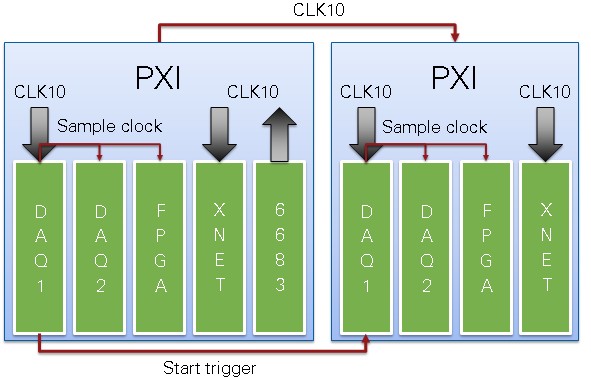
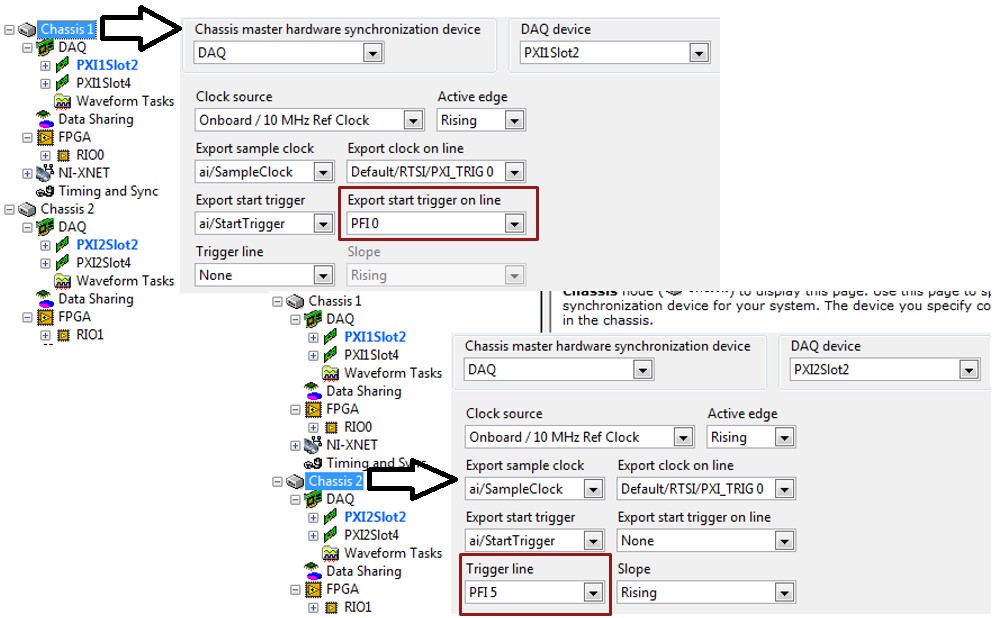
XNET could be used, but in this scenario, the user is not concerned with the time stamping of XNET frames on the bus. Therefore all devices are signal based synchronization single point devices. Since there are multiple chassis, care must be taken to ensure signal based synchronization between chassis. Accomplish this is by sharing chassis reference clocks between chassis via the built in 10 MHz in/out BNCs on the back of most PXI chassis, and then exporting and importing start triggers between the chassis master devices in each chassis. See Figure 6 and Figure 7.
A CPU could be in each chassis, or a single CPU in one chassis, or a single CPU from a separate PC like a desktop or rack mount computer and connected via MXI. If each PXI chassis has different CPUs, be sure to configure NI VeriStand to deploy to the chassis waiting for the start trigger first. See Figure 8.
Waveform acquisition could be used, but in this scenario the user is either not concerned with waveform acquisition or is not concerned with the time stamps in their waveform data logs.
When viewing data logs, time correlation is accomplished via logging channel data values along with the System Time channel and displaying in in X / Y format.
Synchronization of single point devices for each controller can be proved by graphing the HP Loop Duration system channel in NI VeriStand. If this value settles and does not drift over time, the single point devices for that controller are synchronized.
When using multiple controllers with reflective memory, single point synchronization between controllers can be proved by observing no ring read or ring write late counts in the reflective memory status channels. If the controllers are not using reflective memory, a reference signal (sinewave) must be acquired on a device from each controller, logged with System Time from each controller, and plotted on an X / Y graph (2D Axis System in DIAdem).
Figure 6. DAQ1 is chassis master of each chassis. Chassis reference clock is shared between chassis. DAQ1 exports a start trigger to DAQ1.
Figure 7. Configuration of exporting and importing start triggers from DAQ chassis master devices in two different chassis.
Figure 8. Two controllers being deployed to sequentially to ensure trigger readiness
#3. Hardware Timed Single Point DAQ and FPGA via MXIe RIO
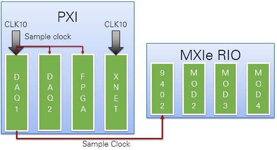
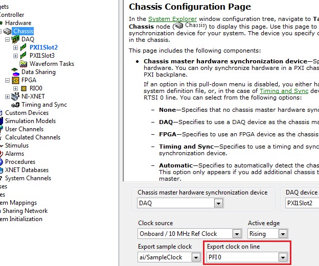
When using multiple MXIe RIOs in single point mode, or mixing them with other hardware timed single point PXI devices, you must facilitate the sharing of sample clock between all devices, including the MXIe RIO chassis. To create your MXIe RIO bitfiles using an external line for sharing sample clock, see note in the NI VeriStand FPGA template document. Once that is done, MXIe RIO behaves almost like an in-chassis PXI FPGA device. The only exception is that it cannot reference its internal clocks to chassis clock, so waveform acquisition without drift is not possible. Figure 9 is an example topology and Figure 10 is an example software configuration. XNET could be used, but in this scenario, the user is not concerned with the time stamping of XNET frames on the bus. Therefore all devices are signal based synchronization single point devices.
A CPU could be in the PXI chassis or a CPU from a separate PC like a desktop or rack mount computer and connected via MXI.
Waveform acquisition could be used, but in this scenario the user is either not concerned with waveform acquisition or is not concerned with the time stamps in their waveform data logs.
When viewing data logs, time correlation is accomplished via logging channel data values along with the System Time channel and displaying in in X / Y format.
Synchronization of single point devices can be proved by graphing the HP Loop Duration system channel in NI VeriStand. If this value settles and does not drift over time, the single point devices are synchronized.
Figure 9. One PXI chassis and one MXIe RIO sharing a single point sample clock. If using more than one MXIe RIO, split the sample clock line.
Figure 10. Configuration of exporting a sample clock on PXI_Trig0 (default) and selecting PFI 0
#4. Hardware Timed Single Point with XNET Time, Single Chassis
In this scenario, the user is interested in the time stamping of XNET frames in relation to other events like hardware sampling and/or software variables. There is a mix of devices, signal based synchronization single point devices and signal and time based XNET frame time stamps. NI VeriStand's automatic configuration will handle the signal based single point devices within one chassis without user intervention. However, a time based synchronization module must be added to the configuration to keep system time and chassis clock from drifting from each other. Configure this in NI VeriStand using the Chassis TimeSync Custom Device. See Figure 11 and Figure 12.
The CPU could be inside the PXI chassis or from a separate PC like a desktop or rack mount computer and connected via MXI.
Because system time and chassis clocks are synchronized, waveform acquisition could be used in this scenario without time drift and waveform data logs could be correlated with other data in post processing.
When viewing data logs, time correlation is accomplished via logging channel data values along with the Absolute Time channel and displaying in in X / Y format along with XNET Raw Frame data logs displayed in X / Y format. Waveform data logs can also be dropped on the same graph once the appropriate X offset is calculated. See Viewing Time Correlated NI VeriStand Data Logs for a tutorial including a time alignment DIAdem SCRIPT, example files, and step by step instructions.
Synchronization of single point devices can be proved by graphing the HP Loop Duration system channel in NI VeriStand. If this value settles and does not drift over time, the single point devices are synchronized.
Synchronization between time and signal based synchronization devices can be proved by acquiring a reference signal from several devices, logging the acquired values along with time information, and plotting the data on a graph as shown in Viewing Time Correlated NI VeriStand Data Logs.
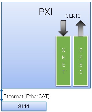
Figure 11. The PXI-6683 drives chassis clock and disciplines system time to match, keeping hardware time and software System Time from drifting. When using PXI Express, use a 6683H or other express compatible time based synchronization module.
Figure 12. Configuration of the Chassis TimeSync Custom Device to select the 6683
#5. Hardware Timed Single Point with XNET Time, Single Controller, Multiple Chassis
In this scenario, the user is interested in the time stamping of XNET frames in relation to other events like hardware sampling and/or software variables. There is a mix of devices, signal based synchronization single point devices and signal and time based XNET frame time stamps. Since there are multiple chassis, care must be taken to ensure signal based synchronization between chassis. Accomplish this is by sharing chassis reference clocks between chassis via the built in 10 MHz in/out BNCs on the back of most PXI chassis, and then exporting and importing start triggers between the chassis master devices in each chassis. Also, a time based synchronization module must be added to the configuration to keep system time and chassis clock from drifting from each other. Configure this in NI VeriStand using the Chassis TimeSync Custom Device. See Figure 12, 13, and 14.
The CPU could be inside one of the PXI chassis or from a separate PC like a desktop or rack mount computer and connected via MXI.
Because system time and chassis clocks are synchronized, waveform acquisition could be used in this scenario without time drift and waveform data logs could be correlated with other data in post processing.
When viewing data logs, time correlation is accomplished via logging channel data values along with the Absolute Time channel and displaying in in X / Y format along with XNET Raw Frame data logs displayed in X / Y format. Waveform data logs can also be dropped on the same graph once the appropriate X offset is calculated. See Viewing Time Correlated NI VeriStand Data Logs for a tutorial including a time alignment DIAdem SCRIPT, example files, and step by step instructions.
Synchronization of single point devices can be proved by graphing the HP Loop Duration system channel in NI VeriStand. If this value settles and does not drift over time, the single point devices are synchronized.
Synchronization between time and signal based synchronization devices can be proved by acquiring a reference signal from several devices, logging the acquired values along with time information, and plotting the data on a graph as shown in Viewing Time Correlated NI VeriStand Data Logs.
Figure 12. DAQ1 is chassis master of each chassis. Chassis reference clock is shared between chassis. DAQ1 exports a start trigger to DAQ1. The PXI-6683 drives chassis clock and disciplines system time to match, keeping hardware time and software System Time from drifting. When using PXI Express, use a 6683H or other express compatible time based synchronization module.
Figure 13. Configuration of exporting and importing start triggers from DAQ chassis master devices in two different chassis.
Figure 14. Configuration of the Chassis TimeSync Custom Device to select the 6683
#6. Hardware Timed Single Point with XNET Time, Multiple Controllers, Multiple Chassis
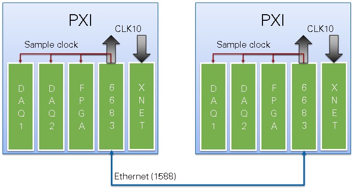
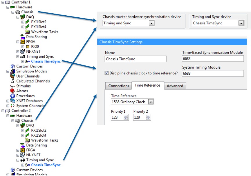
In this scenario, the user is interested in the time stamping of XNET frames in relation to other events like hardware sampling and/or software variables. There is a mix of devices, signal based synchronization single point devices and signal and time based XNET frame time stamps. Since there are multiple chassis and controllers, care must be taken to ensure signal based synchronization between chassis and time synchronization between controllers. A time based synchronization module must be added to the configuration for each controller/chassis pair to effectively share time and chassis clocks. The time based synchronization modules can use 1588 over Ethernet to elect a time master and share time. Alternatively they could all be connected to an external time reference like 1588, GPS, IRIG, or PPS. The time based synchronization modules also override the existing chassis clock with a time-reference-disciplined chassis clock. Configure this in NI VeriStand using the Chassis TimeSync Custom Device. To phase align the signal based single point devices in each chassis, the time based synchronization module generates a sample clock in each chassis. Configure this in NI VeriStand by using the Chassis TimeSync Custom Device as the chassis master device. See Figure 15 and 16.
The CPU could be inside each of the PXI chassis or from a separate PC like a desktop or rack mount computer and connected via MXI to each chassis.
Because system time and chassis clocks are synchronized, waveform acquisition could be used in this scenario without time drift and waveform data logs could be correlated with other data in post processing.
When viewing data logs, time correlation is accomplished via logging channel data values along with the Absolute Time channel and displaying in in X / Y format along with XNET Raw Frame data logs displayed in X / Y format. Waveform data logs can also be dropped on the same graph once the appropriate X offset is calculated. See Viewing Time Correlated NI VeriStand Data Logs for a tutorial including a time alignment DIAdem SCRIPT, example files, and step by step instructions.
Synchronization of single point devices for each controller can be proved by graphing the HP Loop Duration system channel in NI VeriStand. If this value settles and does not drift over time, the single point devices for that controller are synchronized.
When using reflective memory, single point synchronization between controllers can be proved observing no ring read or ring write late counts in the reflective memory status channels. If the controllers are not using reflective memory and to show synchronization between time and signal based devices, a reference signal (sinewave) must be acquired on a device from each controller, logged with Absolute Time from each controller, and plotted on an X / Y graph. See Viewing Time Correlated NI VeriStand Data Logs.
Figure 15. Time is shared between controllers using 1588 with the PXI-6683. The PXI-6683 drives chassis clock and disciplines system time to match, keeping hardware time and software System Time from drifting. The PXI-6683 in each chassis also generates a sample clock phase aligned to round multiples of the period in system time. When using PXI Express, use a 6683H or other express compatible time based synchronization module.
#7. EtherCAT Single Point, Single Chassis
XNET could be used, but in this scenario, the user is not concerned with the time stamping of XNET frames on the bus. Therefore all devices are time based synchronization single point devices so no additional synchronization solution is needed. When adding the Scan Engine and EtherCAT Custom Device, be sure to check Synchronize NI VeriStand to Scan Engine. See Figure 17 and 18.
The CPU could be inside the PXI chassis or from a separate PC like a desktop or rack mount computer and connected via MXI.
Waveform acquisition could be used, but in this scenario the user is either not concerned with waveform acquisition or is not concerned with the time stamps in their waveform data logs.
When viewing data logs, time correlation is accomplished via logging channel data values along with the System Time channel and displaying in in X / Y format.
Figure 17. EtherCAT single point IO and XNET signals. Nothing is used to keep software System Time and hardware time from drifting.
Figure 18. Scan Engine and EtherCAT Custom Device setting to clock the NI VeriStand Primary Control Loop from Scan Engine
#8. EtherCAT Single Point with XNET Time, Single Chassis
In this scenario, the user is interested in the time stamping of XNET frames in relation to other events like hardware sampling and/or software variables. There is a mix of devices, time based synchronization single point devices and signal and time based XNET frame time stamps. A time based synchronization module must be added to the configuration to keep system time and chassis clock from drifting from each other. Configure this in NI VeriStand using the Chassis TimeSync Custom Device. When adding the Scan Engine and EtherCAT Custom Device, be sure to check Synchronize NI VeriStand to Scan Engine. See Figure 19, 20, and 21.
The CPU could be inside the PXI chassis or from a separate PC like a desktop or rack mount computer and connected via MXI.
Because system time and chassis clocks are synchronized, waveform acquisition could be used in this scenario without time drift and waveform data logs could be correlated with other data in post processing.
When viewing data logs, time correlation is accomplished via logging channel data values along with the Absolute Time channel and displaying in in X / Y format along with XNET Raw Frame data logs displayed in X / Y format. Waveform data logs can also be dropped on the same graph once the appropriate X offset is calculated. See Viewing Time Correlated NI VeriStand Data Logs for a tutorial including a time alignment DIAdem SCRIPT, example files, and step by step instructions.
Synchronization between time and signal based synchronization devices can be proved by acquiring a reference signal from several devices, logging the acquired values along with time information, and plotting the data on a graph as shown in Viewing Time Correlated NI VeriStand Data Logs.
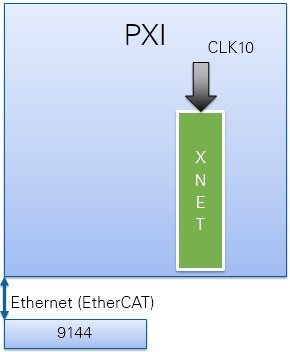
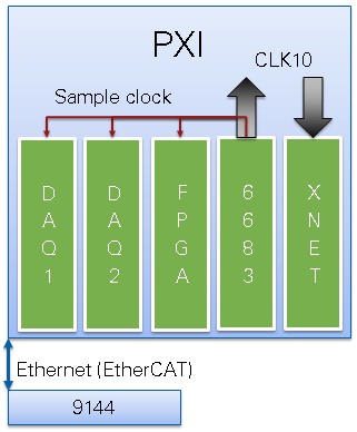
Figure 19. EtherCAT single point IO and XNET signals. The PXI-6683 drives chassis clock and disciplines system time to match, keeping hardware time and software System Time from drifting. When using PXI Express, use a 6683H or other express compatible time based synchronization module.
Figure 20. Scan Engine and EtherCAT Custom Device setting to clock the NI VeriStand Primary Control Loop from Scan Engine
Figure 21. Configuration of the Chassis TimeSync Custom Device to select the 6683
#9. EtherCAT Single Point with XNET Time, Multiple Controllers, Multiple Chassis
In this scenario, the user is interested in the time stamping of XNET frames in relation to other events like hardware sampling and/or software variables. There is a mix of devices, time based synchronization single point devices and signal and time based XNET frame time stamps. Since there are multiple chassis and controllers, care must be taken to ensure signal based synchronization between chassis and time synchronization between controllers. A time based synchronization module must be added to the configuration for each controller/chassis pair to effectively share time and chassis clocks. The time based synchronization modules can use 1588 over Ethernet to elect a time master and share time. Alternatively they could all be connected to an external time reference like 1588, GPS, IRIG, or PPS. The time based synchronization modules also override the existing chassis clock with a time-reference-disciplined chassis clock. Configure this in NI VeriStand using the Chassis TimeSync Custom Device. When adding the Scan Engine and EtherCAT Custom Device, be sure to check Synchronize NI VeriStand to Scan Engine. The Scan Engine always starts aligned to round multiples of the period in system time, ensuring that I/O scanning is phase aligned across controllers. See Figure 22, 23, and 24.
The CPU could be inside each of the PXI chassis or from a separate PC like a desktop or rack mount computer and connected via MXI to each chassis.
Because system time and chassis clocks are synchronized, waveform acquisition could be used in this scenario without time drift and waveform data logs could be correlated with other data in post processing.
When viewing data logs, time correlation is accomplished via logging channel data values along with the Absolute Time channel and displaying in in X / Y format along with XNET Raw Frame data logs displayed in X / Y format. Waveform data logs can also be dropped on the same graph once the appropriate X offset is calculated. See Viewing Time Correlated NI VeriStand Data Logs for a tutorial including a time alignment DIAdem SCRIPT, example files, and step by step instructions.
Synchronization between time and signal based synchronization devices can be proved by acquiring a reference signal from several devices, logging the acquired values along with time information, and plotting the data on a graph as shown in Viewing Time Correlated NI VeriStand Data Logs.
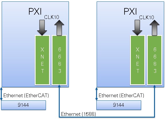
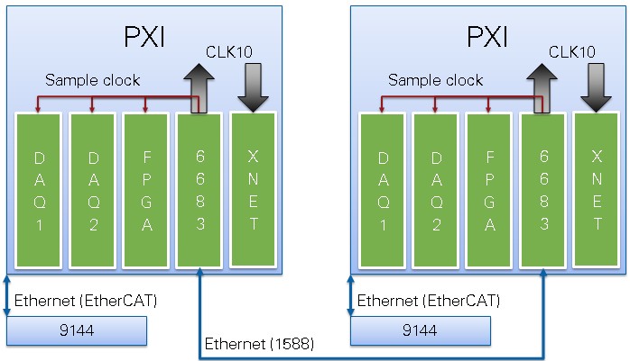
Figure 22. Time is shared between controllers using 1588 with the PXI-6683. The PXI-6683 drives chassis clock and disciplines system time to match, keeping hardware time and software System Time from drifting. When using PXI Express, use a 6683H or other express compatible time based synchronization module.
Figure 23. Scan Engine and EtherCAT Custom Device setting to clock the NI VeriStand Primary Control Loop from Scan Engine
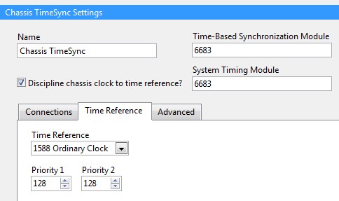
Figure 24. Configuration of the Chassis TimeSync Custom Device to select the 6683 and the time reference as 1588
#10 EtherCAT & DAQ and/or FPGA Single Point, Single Chassis
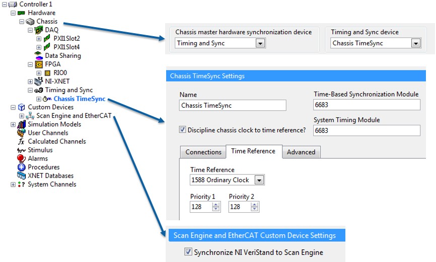
In this scenario, because EtherCAT & hardware timed DAQ and/or FPGA are used for single point data, there is a mix of time and signal based single point devices. Therefore a time based synchronization module must be used for the single point devices which will also automatically enable time alignment of XNET time stamps. To phase align the signal based single point devices with time based single point EtherCAT, the time based synchronization module generates a sample clock for them to use. Configure this in NI VeriStand using the Chassis TimeSync Custom Device as the chassis master device. When adding the Scan Engine and EtherCAT Custom Device, be sure to check Synchronize NI VeriStand to Scan Engine. See Figure 25 and 26.
The CPU could be inside the PXI chassis or from a separate PC like a desktop or rack mount computer and connected via MXI.
Because system time and chassis clocks are synchronized, waveform acquisition could be used in this scenario without time drift and waveform data logs could be correlated with other data in post processing.
When viewing data logs, time correlation is accomplished via logging channel data values along with the Absolute Time channel and displaying in in X / Y format along with XNET Raw Frame data logs displayed in X / Y format. Waveform data logs can also be dropped on the same graph once the appropriate X offset is calculated. See Viewing Time Correlated NI VeriStand Data Logs for a tutorial including a time alignment DIAdem SCRIPT, example files, and step by step instructions.
Synchronization of single point devices can be proved by graphing the HP Loop Duration system channel in NI VeriStand. If this value settles and does not drift over time, the single point devices are synchronized.
Synchronization between time and signal based synchronization devices can be proved by acquiring a reference signal from several devices, logging the acquired values along with time information, and plotting the data on a graph as shown in Viewing Time Correlated NI VeriStand Data Logs.
Figure 25. The PXI-6683 drives chassis clock and disciplines system time to match, keeping hardware time and software System Time from drifting. The PXI-6683 also generates a sample clock phase aligned with the EtherCAT scan for signal based devices.When using PXI Express, use a 6683H or other express compatible time based synchronization module.
#11 EtherCAT & DAQ and/or FPGA Single Point, Multiple Chassis
In this scenario, because EtherCAT & hardware timed DAQ and/or FPGA are used for single point data, there is a mix of time and signal based single point devices. Therefore a time based synchronization module must be used for the single point devices which will also automatically enable time alignment of XNET time stamps. To phase align the signal based single point devices with time based single point EtherCAT, the time based synchronization module generates a sample clock for them to use. Configure this in NI VeriStand using the Chassis TimeSync Custom Device as the chassis master device. When adding the Scan Engine and EtherCAT Custom Device, be sure to check Synchronize NI VeriStand to Scan Engine. Additional chassis can share the chassis clock and use the sample clock from the time based synchronization module as a start trigger. Accomplish this is by sharing chassis reference clocks between chassis via the built in 10 MHz in/out BNCs on the back of most PXI chassis, and then exporting and importing start triggers between the chassis master devices in each chassis. See Figure 27 and 28.
The CPU could be inside the PXI chassis or from a separate PC like a desktop or rack mount computer and connected via MXI.
Because system time and chassis clocks are synchronized, waveform acquisition could be used in this scenario without time drift and waveform data logs could be correlated with other data in post processing.
When viewing data logs, time correlation is accomplished via logging channel data values along with the Absolute Time channel and displaying in in X / Y format along with XNET Raw Frame data logs displayed in X / Y format. Waveform data logs can also be dropped on the same graph once the appropriate X offset is calculated. See Viewing Time Correlated NI VeriStand Data Logs for a tutorial including a time alignment DIAdem SCRIPT, example files, and step by step instructions.
Synchronization of single point devices can be proved by graphing the HP Loop Duration system channel in NI VeriStand. If this value settles and does not drift over time, the single point devices are synchronized.
Synchronization between time and signal based synchronization devices can be proved by acquiring a reference signal from several devices, logging the acquired values along with time information, and plotting the data on a graph as shown in Viewing Time Correlated NI VeriStand Data Logs.
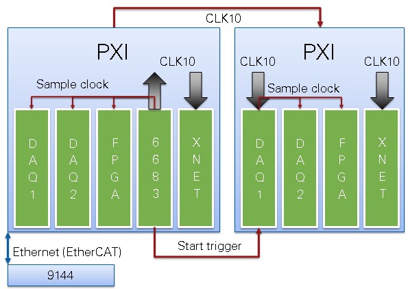
Figure 27. The PXI-6683 drives chassis clock and disciplines system time to match, keeping hardware time and software System Time from drifting. The PXI-6683 also generates a sample clock phase aligned with the EtherCAT scan for signal based devices.The second chassis shares the chassis clock and DAQ1 receives a start trigger from the PXI-6683. When using PXI Express, use a 6683H or other express compatible time based synchronization module.
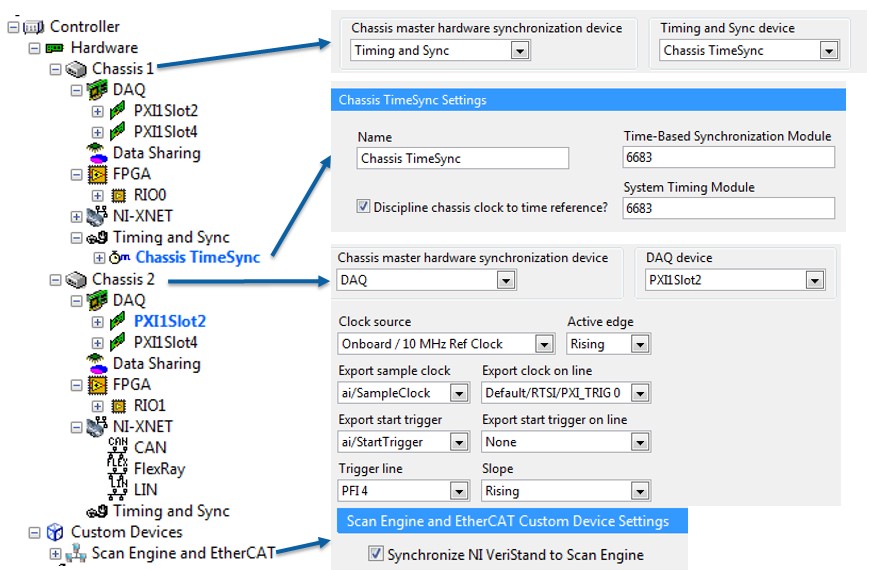
#12 EtherCAT & DAQ and/or FPGA Single Point, Multiple Chassis and Controllers
In this scenario, because EtherCAT & hardware timed DAQ and/or FPGA are used for single point data, there is a mix of time and signal based single point devices. Therefore a time based synchronization module must be used for the single point devices which will also automatically enable time alignment of XNET time stamps. Since there are multiple chassis and controllers, care must be taken to ensure signal based synchronization between chassis and time synchronization between controllers. A time based synchronization module must be added to the configuration for each controller/chassis pair to effectively share time and chassis clocks. The time based synchronization modules can use 1588 over Ethernet to elect a time master and share time. Alternatively they could all be connected to an external time reference like 1588, GPS, IRIG, or PPS. The time based synchronization modules also override the existing chassis clock with a time-reference-disciplined chassis clock. To phase align the signal based single point devices with time based single point EtherCAT, the time based synchronization module generates a sample clock for them to use. Configure this in NI VeriStand using the Chassis TimeSync Custom Device as the chassis master device. When adding the Scan Engine and EtherCAT Custom Device, be sure to check Synchronize NI VeriStand to Scan Engine. See Figure 29 and 30.
The CPU could be inside each of the PXI chassis or from a separate PC like a desktop or rack mount computer and connected via MXI to each chassis.
Because system time and chassis clocks are synchronized, waveform acquisition could be used in this scenario without time drift and waveform data logs could be correlated with other data in post processing.
When viewing data logs, time correlation is accomplished via logging channel data values along with the Absolute Time channel and displaying in in X / Y format along with XNET Raw Frame data logs displayed in X / Y format. Waveform data logs can also be dropped on the same graph once the appropriate X offset is calculated. See Viewing Time Correlated NI VeriStand Data Logs for a tutorial including a time alignment DIAdem SCRIPT, example files, and step by step instructions.
Synchronization of single point devices for each controller can be proved by graphing the HP Loop Duration system channel in NI VeriStand. If this value settles and does not drift over time, the single point devices for that controller are synchronized.
When using reflective memory, single point synchronization between controllers can be proved observing no ring read or ring write late counts in the reflective memory status channels. If the controllers are not using reflective memory and to show synchronization between time and signal based devices, a reference signal (sinewave) must be acquired on a device from each controller, logged with Absolute Time from each controller, and plotted on an X / Y graph. See Viewing Time Correlated NI VeriStand Data Logs.
Figure 29. Time is shared between controllers using 1588 with the PXI-6683. The PXI-6683 drives chassis clock and disciplines system time to match, keeping hardware time and software System Time from drifting. The PXI-6683 in each chassis also generates a sample clock phase to with EtherCAT for signal based devices. When using PXI Express, use a 6683H or other express compatible time based synchronization module.
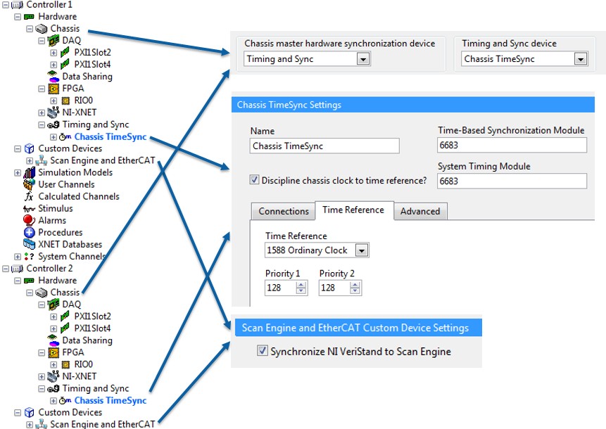
Figure 30. Each target is configured identically. The Chassis TimeSync Custom Device is set to use the PXI-6683, share time over 1588, and is selected as the chassis master device. The Scan Engine and EtherCAT Custom Device setting to clock the NI VeriStand Primary Control Loop from Scan Engine.
