Part III: How To Reduce Errors When Switching Low Resistances
Overview
This tutorial is part 1 of a three part series that discusses switching low-level voltage,current, and resistances. Each tutorial in this series, will provide you with insights on low-level switching for various different applications and measurement types. This tutorial introduces and discusses the techniques and challenges when switching low-voltage signals.
The other tutorials in this series are:
Contents
- Switching Low Resistances
- 4-Wire Resistor Measurements
- Offset Compensation
- Low Path Resistance
- Conclusion
- Relevant NI Products and Tutorials
Switching Low Resistances
Special techniques need to be implemented when measuring resistances under 100 Ω. These types of resistor values are generally encountered when measuring contact resistance and testing cable continuity. This section of the paper assumes measurements of resistors is being taken with a digital multimeter and will discuss ways to eliminate errors due to switch contact resistance.
4-Wire Resistor Measurements
The best setup for low-resistance measurements is the 4-wire setup. A 4-wire setup utilizes four leads, two leads to drive current through a resistance and two leads to measure the voltage drop across that resistance. Traditional 4-wire measurements require that the power is off in the circuit so that the measured voltage drop is due only to the supplied current. Thus traditionally, the power to a circuit must be turned off before any measurements are taken. Figure 1 illustrates a 4-wire setup. The black leads measure the voltage drop. The blue leads connect the test current, which is 1 mA in the 100 Ω range.
Figure 1. Digital Multimeter Setup
In every resistance measurement, the digital multimeter must supply a test current, 1 mA in this setup, and then measure the voltage drop across the unit under test. The measured voltage drop is then used in the calculation for resistance, thus its accuracy is very important. This accuracy can be negatively affected by thermal offsets in switches or relays. There are several techniques that can help minimize the effects of thermal offset arising from a given relay. One of the most prevalent methods is called offset compensation discussed in the next section.
Offset Compensation
Thermal emf is a phenomenon in which an error voltage is induced in to a circuit due to the formation of a thermocouple between the leads of a relay and the PCB trace, which are often made of different metals. Offset compensation is a method used to measure the offset potential of the switch and calibrate it out of the measurement. Some DMMs such as the NI PXI-4070 FlexDMM have built in capability to make this measurement and account for it. Offset compensation overcomes the requirements of multiple voltage measurements, external current excitation sources, and additional calculations, yet is still able to measure the actual offset voltage and take it out of the resistance measurement.
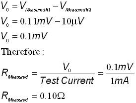
Once enabled on the DMM and without any additional user interaction, offset compensation invokes the DMM to take two resistance measurements, but with the test current source off during the second measurement. The first measurement includes the voltage drop across the relay and any thermal emfs that may be present as shown in Figure 2.
Figure 2: DMM Measuring Total Potential Drop across a Reed Relay
During the second measurement the current source is turned off so the voltage drop across the relay becomes zero volts. This second measurement measures only the thermal offset as shown in Figure 3.
Figure 3: Second Measurement Made by DMM to Determine Thermal EMF or Offset
The DMM then subtracts the second measurement from the first to determine the offset-compensated voltage (VC). This voltage is then used to determine the correct resistance value as shown in the equations below:
Low Path Resistance
In addition to using appropriate methods such as offset compensation it is important to choose relays that have low path resistance when taking low-resistance measurements because the resistance added by a relay is in series with the source resistance and can considerably increase the total resistance value seen by the DMM. FET switches have particularly high path resistance and should not be used when taking low-resistance measurements.
Conclusion
View Part I and Part II of this tutorial series to learn more about low-level switching:
Relevant NI Products and Tutorials
Customers interested in this topic were also interested in the following NI products:


