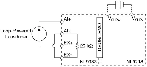
Connection Diagram for Loop Powered Sensors with the NI 9218
Overview
This article provides the connection diagram for loop powered sensors for use with the NI 9218. This information is helpful if you are getting unexpected readings while using a loop powered or two wire current transducer with the NI 9218 module and NI 9983D/L/F measurement adapter.
Introduction
Below is a diagram of how to connect the loop powered transducer to the NI 9983 and NI 9218.
Figure 1. Wiring with a Loop Powered Current Transducer.
Note: An external short must be made between AI- and EX-. Without this short the voltage signal may exceed the common mode with respect to EX- and cause the NI 9218 to read incorrect current signals. For 4 wire transducers the NI 9218 does not need to be shorted between AI- and EX- since there are independent connections for AI+ and AI-.
For additional information on how to wire the external power supply and perform the transducer connection please see Figure 3. in the Design a Current Loop System.
