4 Game-Changing Underlying Technologies for Advanced Radar
Overview
This evolution presents new challenges for scientists and engineers who are designing and testing intelligence, surveillance, and reconnaissance (ISR) systems. These challenges offer opportunities for innovation as engineers are asked to develop increasingly complex systems using more cost- and time-effective methods.
Yet, the underlying technologies that enable these sophisticated systems are also evolving to meet these challenges. As a provider of instrumentation and test equipment used for radar design and test, NI believes the following four recent innovations will have the biggest enabling impact on radar technology over the next several years.
Contents
- Gallium Nitride for Front-End Components
- High-Speed Data Converters for Transmit and Receive
- Evolving FPGA Technology for Cognitive Techniques
- High-Bandwidth Data Buses for Sensor Fusion
- Bringing It All Together With Modular, COTS Instruments
Gallium Nitride for Front-End Components
Gallium Nitride (GaN), considered by some to be the biggest semiconductor innovation since silicon, is a material that is capable of operating at a much higher voltage than conventional semiconductor material. Higher voltage means better efficiency, so RF power amplifiers and attenuators using GaN consume less power and produce less heat. As more GaN-based RF component suppliers enter the market with production-ready, reliable products, the use of GaN-based amplifiers has increased.
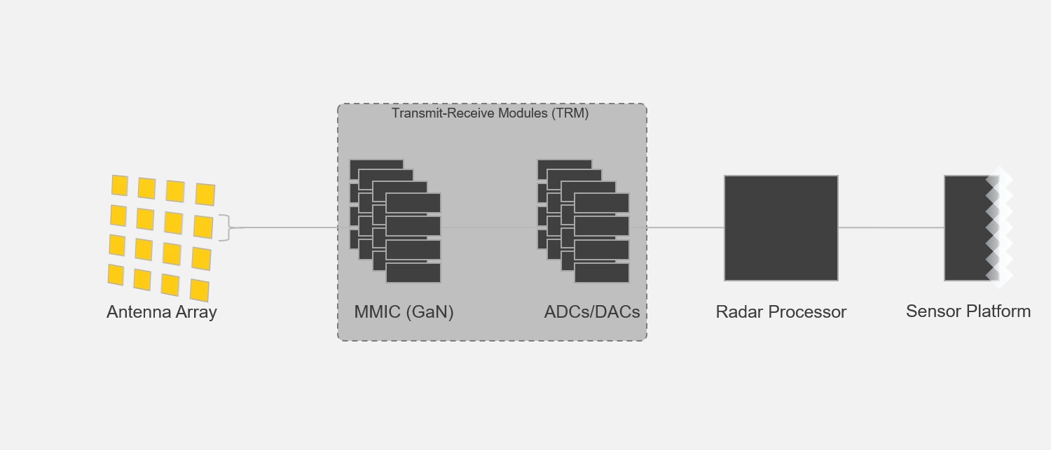
This technology is important for the evolution of active electronically scanned array (AESA) radar systems. An AESA is a fully active array with hundreds or thousands of antennas, each with its own phase and gain control. Using a phased array of transmitters and receivers, these radar systems steer beams electronically without physically moving the antenna. These types of radar systems are growing in popularity because of their increased power on target, spatial resolution, and improved robustness compared with other conventional radars. For example, if one element in the array fails, the radar continues to operate. The increased use of GaN amplifiers in AESA radars should offer better performance, achieving equivalent output power with smaller form factors and requiring less cooling.
Figure 1: AESA Radar Architecture
As applications and solutions using GaN technology grow more advanced, correlating component-level test results with those at a system level becomes more critical. Traditional methods of component test using vector network analyzers provide an accurate and narrowband view of forward and reflected gain and phase. However, the continuous wave (CW) stimulus in this popular method does not accurately reflect the actual signal environment the component is ultimately used in. As an alternative, you can take advantage of the wideband flexibility of vector signal analyzers and vector signal generators to create pulses and modulated stimuli more representative of real-world applications and their environments. Combining this capability with S-parameter analysis is an increasingly more strategic method of testing at a component level.
High-Speed Data Converters for Transmit and Receive
Converter technology continues to evolve every year. Today’s analog-to-digital converters (ADCs) and digital-to-analog converters (DACs) from major semiconductor companies sample at rates orders of magnitude faster than that of their predecessors five years ago at comparable resolutions. The increased resolution of these high-speed ADCs provides radars with higher dynamic range and wide instantaneous bandwidth. Dynamic range is a critical factor for maximum operating range; for example, it enables fifth-generation fighters such as the F-35 to identify targets much farther out. More instantaneous bandwidth provides several advantages, including increased spatial resolution through pulse compression and the ability to implement advanced techniques such as low probability of intercept (LPI) radar. Another trend enabled by wider bandwidth is sensor fusion, during which you can allocate a single signal chain to multiple functions. For example, you can use a wideband sensor as both a communications system and a radar simultaneously by splitting multiple waveform types across multiple frequency bands.
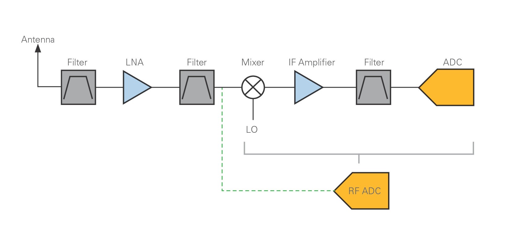
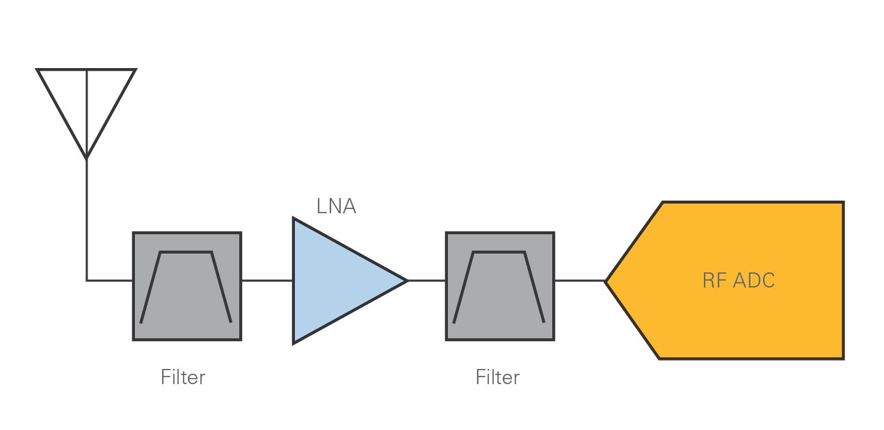
Additionally, many semiconductor companies are releasing ADCs and DACs called “direct RF sampling converters,” such as the TI ADC12DJ3200 , which acquires data at rates up to 6.4 GS/s. With 12-bit resolution at these sample rates, RF sampling converters can directly convert RF input signals up to C band without upconversion or downconversion. As converters continue to evolve, future radars will benefit from direct RF sampling in both the C and X bands.
Figure 2: Heterodyne Versus Direct RF Sampling Architecture
NI's PXI FlexRIO IF Transceiver, for instance, will revolutionize AESA radars. In a fully active array, each antenna element requires its own ADC and DAC. That means if the ADCs and DACs cannot directly sample at the radar’s operating frequency, each transmit-receive module (TRM) also requires its own upconversion/downconversion stage. This leads to increased design costs, size, and variation in performance. But you can reduce costs, size, and complexity by using a direct RF sampling architecture to simplify the RF front-end architecture by eliminating the mixer and local oscillator (LO). With such a large array of transmitters and receivers, direct RF sampling architectures can significantly increase channel density and reduce the cost per channel.
Because of its modular approach to instrumentation, NI rapidly delivers the latest converters to market before they are widely available in commercial instruments. NI’s latest FlexRIO transceiver, for instance, uses direct RF sampling converters to sample up to 6.4 GS/s. This helps researchers and engineers rapidly prototype with real-world I/O and develop test benches that match the cutting-edge performance of today’s radars. These devices are also capable of leveraging PXI’s advanced timing and synchronization backplane to enable phase coherence across dozens to hundreds of channels in a single system.
Evolving FPGA Technology for Cognitive Techniques
FPGA technology also continues to improve. Modern FPGAs contain significantly more logic, provide more computational power per watt, and support high-speed data streaming at up to 150 Gb/s with dedicated IP blocks. The increased computational capability of today’s FPGAs opens the door for innovative techniques that simply weren’t possible five years ago.
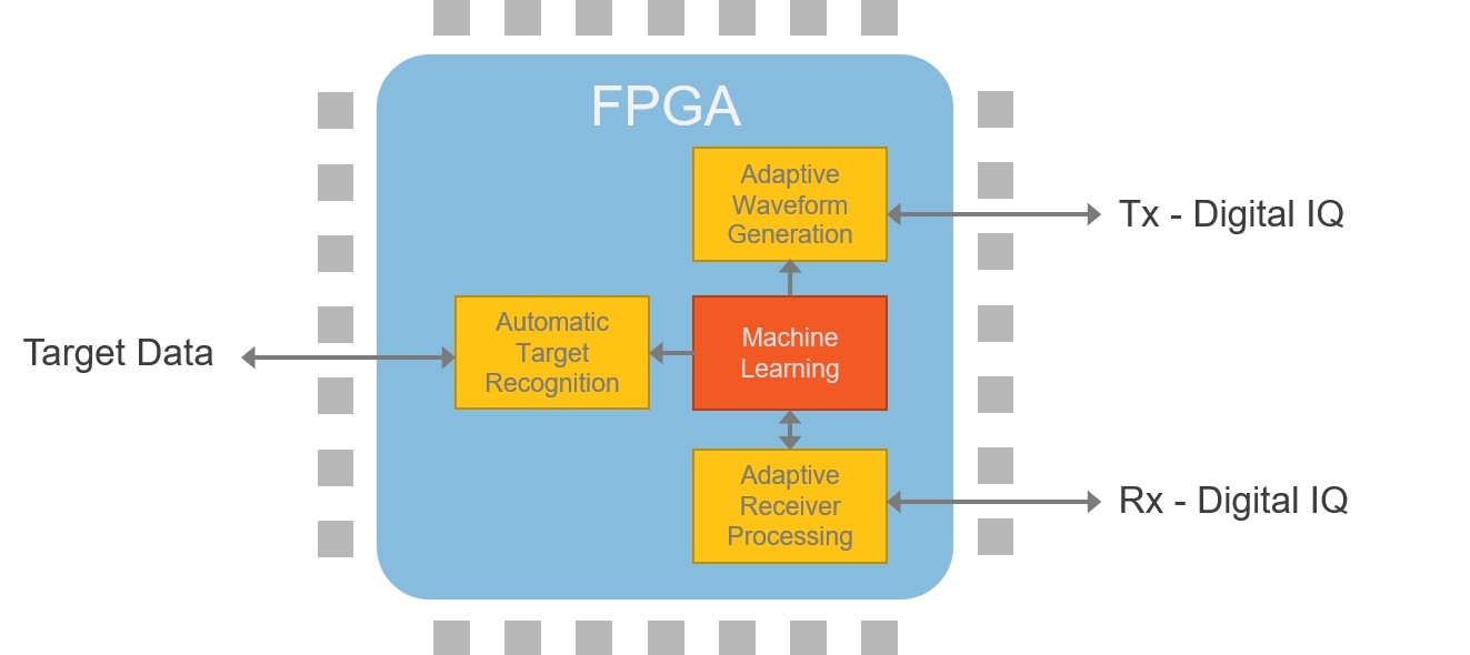
One area of innovation that is enabled by new FPGA technology is the application of machine learning techniques within cognitive radar. These techniques make radars more responsive to their environments so they provide more actionable insight. Instead of operating modes that are pre-programmed (searching mode, tracking mode, etc.), machine learning allows radars to automatically adapt to the best operating parameters, including operating frequency and waveform types. Machine learning also unlocks capabilities such as automatic target recognition (ATR) and facilitates knowledge-aided operation.
Figure 3: Machine Learning Techniques Implemented on the FPGA Within Cognitive Radar
While aerospace and defense organizations have been using FPGA technology for many years, another evolution we have seen is in the advancement of higher level FPGA design tools. Higher level tools can improve development efficiency by simplifying the migration host-based algorithms to FPGAs, while integrating low-level HDLs in the design. In the case of LabVIEW FPGA, you can also benefit from the tight NI hardware software integration through the abstraction of board infrastructure such as PCI Express, JESD204B, memory controllers, and clocking. This shifts the focus of FPGA development away from board support toward algorithm design, which decreases development effort without sacrificing performance. More abstracted FPGA tools can be a game changer for shortening development cycles even for software engineers and scientists who don’t have previous VHDL or Verilog expertise or for hardware engineers who are on tight timelines.
High-Bandwidth Data Buses for Sensor Fusion
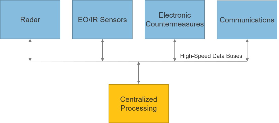
Another key trend is the increasing reliance on higher bandwidth data buses such as PCI Express Gen 3, 40/100 GbE, Fiber Channel, and Xilinx Aurora to move high-bandwidth sensor data back to centralized processors for computation. For example, the F-35’s integrated core processor aggregates data from multiple ISR sensors to enable processing on an aggregate set of data. This provides pilots with better situational awareness. At the heart of this trend is the evolution of high-speed serial transceiver technology (also referred to as multigigabit transceivers or MGTs). This technology has progressed rapidly in recent years, with current line rates topping out at 32 Gbps per lane; 56 Gbps with PAM4 is on the horizon. FPGAs are mainly thought of as processing resources, but they also contain some of the most sophisticated MGTs, which makes them ideal targets for sensor development.
Figure 4: Aggregating Sensor Data From Multiple ISR Sensors for Centralized Processing Using High-Speed Data Buses
The advantage of working with modular instrumentation is that systems can more easily evolve as processing power and bandwidth rapidly increase over time. The PXI platform in particular works well for systems that require high-bandwidth data streaming and integrated timing and synchronization.
Bringing It All Together With Modular, COTS Instruments
With the rapid evolution of these underlying technologies, radar techniques and architectures are increasing both in complexity and capability. As technology continues to advance, systems must evolve to keep pace. With both design talent and an intimate knowledge available in-house, developing fully custom hardware and software for radar prototypes and test systems internally can seem like the only viable option to achieve the required customization and performance. However, these solutions also come with long-term maintenance responsibility, and opportunity cost.
With the advent of the FPGAs and rapid adoption of new converters and streaming technologies in modular form factors, COTS solutions not only meet specification requirements but can offer flexibility to ensure systems achieve the longevity required to longer life cycles. By rapidly incorporating these technologies in modular, COTS form factors, NI enables engineers to meet the evolving requirements of advanced radar systems while also meeting strict timelines and budgets.
