Advanced Rocket Engine Test Architecture for Enhanced System Independence and Maintenance
Overview
This white paper provides a comprehensive guide to designing and implementing rocket engine test facilities. It covers the process of rocket engine testing, the key elements of a rocket test architecture, and critical considerations for test design, such as system latency, timing, and redundancy. The paper details implementation steps, including system identification, technology selection, and system performance validation. It also highlights emerging technologies, like gRPC and iDDS, that enhance communication and data management in test systems
Contents
- How Are Rocket Engines Tested?
- What Is a Rocket Engine Test Stand?
- Rocket Test Architecture
- Considerations for Test Architecture Design
- Implementation Steps
- Emerging Technologies for Rocket Engine Test
- Tailored NI Solutions for Advanced Rocket Engine Testing
- Next Steps
- Footnotes and References
How Are Rocket Engines Tested?
There were more orbital attempts made in 2021 than any previous year in history.1 Companies and governments around the world attempted 146 flights, with 135 successful orbits. 2021 broke the previous record of 139 attempts set at the height of the space race in 1967 as the USSR and USA competed heavily to get to space and beyond. The space race of the 2020s includes more than just two countries. Launches now represent USA, UK, Europe, Russia, China, India, Turkey, Iran, Israel, and others; just the first six months of 2022 saw the trend continue with 72 successful flights. And the race is no longer a government project; many private space companies are competing, bringing large amounts of investor money into the market.
New rocket technologies are enabling this surge in space launches. SpaceX launched 31 Falcon 9 missions in 2021, all of them successfully. Their new approach to rocket design allowed them to launch all these missions using previously used rocket cores—only two new Falcon 9 first stages were introduced to support these launches. As companies and countries continue to invest in making space launch more reliable, reusable, and affordable, the number of launches and the reach of those launches will continue to increase.
The infrastructure to support these launches is increasing as well. There are 35 active spaceports and launch facilities that can support suborbital, orbital, and extraorbital missions. The list of locations spans the globe, including all the continents and more than 13 countries,2 with other countries building new facilities now. And additional sites are used for testing the rockets that launch from those facilities. It’s an exciting time to be part of the space industry.
The FAA regulates rocket launches for any launches on U.S. soil, or outside of the U.S. for any launch by a U.S. citizen or entity.3 Other countries have similar regulations and regulatory bodies; a company cannot launch into space without working through the proper engineering steps. One of those critical steps is to test the rocket vehicle and demonstrate that it has a high likelihood of success.
Testing a rocket starts by testing the various components of the rocket. Engineering teams separately test the materials and components that will make up the structure, the fuels, and the electronics. Those components are then assembled and tested as subsystems, and finally fully assembled into a full stage-level acceptance test.
NI products are used across all aspects of the vehicle. The static and fatigue structural testing platform is ideal for testing the strength of the fuel tank to survive the stress of a flight. NI’s PXI-based modular instruments and automated test software provide a powerful platform for testing the avionics circuitry. NI’s LRU HIL test architecture is ideal for generating a variety of test cases to test avionics controllers.
This paper focuses on testing the rocket engine, but many of the elements will apply to the final full vehicle test as well.
Rocket engine testing is a vital part of testing all rocket engine types; this testing is required to meet FAA regulations. But testing provides value beyond meeting regulations. A NASA report demonstrated that there was a positive correlation between the amount of time spent testing rocket engines and the reliability of those engines.4 Each engine manufacturer must decide how to balance the investment and cost of additional testing and the expected benefit of that testing.
What Is a Rocket Engine Test Stand?
A rocket engine test stand is a structure designed to hold and test rocket engines by providing necessary support and control systems, including hold-down thrust structures, ground support equipment for propellants, cooling systems, exhaust diversion, and automation for safety and operational management during testing. To test a rocket engine, the engine is mounted into a test stand and fired for a limited amount of time. The rocket engine test stand must provide a necessary hold-down thrust structure, ground support equipment for propellants, cooling, diversion, and exhaust, as well as a control system to automate the test and maintain safety throughout operations and testing. Engineers must decide if the rocket will be mounted vertically or horizontally—there are advantages for either orientation. It is easier to correlate measurements to a vertically mounted engine because the forces are more like the forces experienced during flight. But a vertically mounted engine presents a problem of routing the exhaust away from the rocket during the test, which is usually done with a flame diverter.
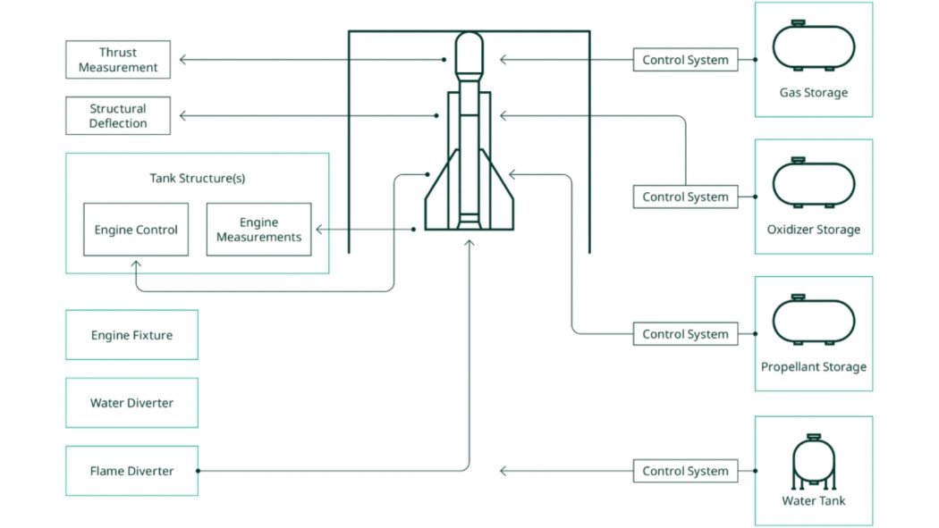
Figure 1. Elements of a Rocket Engine Test Stand
The exhaust poses several challenges to the test facility. In addition to the heat, the exhaust is noisy and dirty. Adding a water deluge to the exhaust can provide a cushion to carry heat away from the engine, and a shield to dampen noise and contaminants from the surrounding community.
There are many variations on a rocket engine test. A standard, sea-level test may be performed on a test stand without a lot of additional equipment, but other tests may require specialized test environments. For example, to test a rocket thruster for attitude control on a satellite in space, the test stand requires a vacuum chamber to replicate the intended operating conditions of the engine. Other tests may require a thermal vacuum chamber or additional mechanical devices to test the engine gimbal.
Test stations also vary based on the stage of the engine development. An early development engine test may include many additional sensors as engineers try to capture more dynamics of the engine performance. A test stand performing qualification or acceptance testing prior to flight duty may test a smaller set of signals that verify proper operation.
An engineering team tasked with designing a rocket test must consider all these potential needs when designing a new test stand. With rocket technology evolving as fast as it is right now, engineers must also plan for tests that might be required in the future. The test design must be powerful enough to meet the known needs, as well as flexible enough to meet the needs as they evolve over time.
NI engineers have worked closely with engineers designing rocket test systems for more than 30 years. Over this time, architectures have matured with the introduction of new technologies and software techniques. Best practices from related applications—jet engine testing, wind tunnels, and other large test facilities—have influenced the design of systems used to test rocket engines. Some key principles have emerged as core to the success of an architectural design to test rocket engines.
A rocket test facility may support a single test stand, or multiple test stands. Each test stand requires support from various subsystems or pads, which may be dedicated to a stand or may be shared among multiple stands or sites within the test facility. A facility-wide ground control system supervisor brings all the pads and test stands together for coordinated operational management of the facility resources.
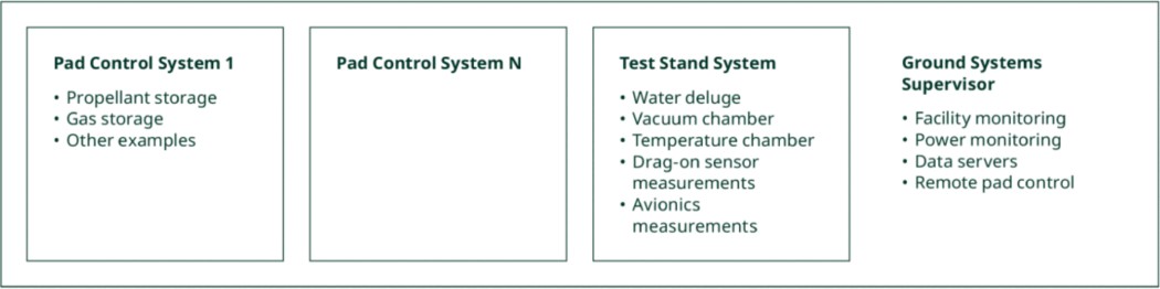
Figure 2. Rocket Test Facility Subsystems
Support pad control systems must provide reliability for control, as well as measurement capabilities to track and improve performance.
Successful implementation of a rocket test site requires careful coordination among these systems. Over the years, a control scheme has developed at major space facilities that provides a design pattern with the flexibility to meet the communication among these systems and the variability of the systems between tests. At space companies that manage both test and launch facilities, many of the components of the pattern are shared, to reduce the differences between what is tested and how it is launched.
Rocket Test Architecture
This architecture uses a system design pattern common among all the test stands and pads. The pattern provides the local control needed by each system, while sharing information among systems to ensure synchronization of test operations.
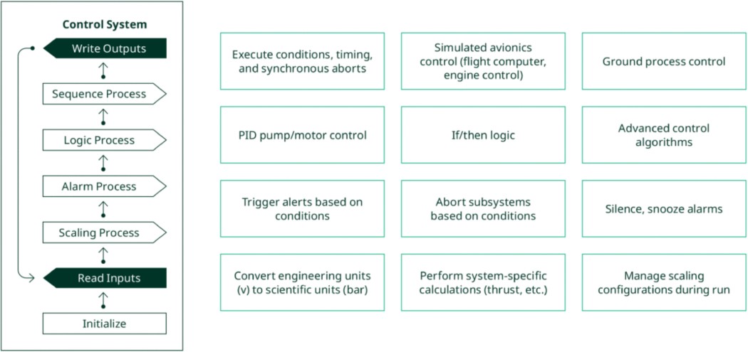
Figure 3. General Control System Design Pattern
In this pattern, control systems read inputs from communication processes described later in this paper.
A scaling process converts these raw units to scientific units appropriate to the subsystem. A scaling process may also combine multiple channels into a single calculated channel—for example, summing all the thrust load cells to provide a single thrust value. A scaling process also applies reconfigurable calibrations, as instrumentation can change between tests or during operations.
An alarm process evaluates the data points’ output from the scaling process to identify alarms. Alarms may be classified into multiple categories, such as alerts to abort a test immediately or to notify an operator of a potential issue. An alarm process may manage the successful shutdown of a test sequence, or it may send commands to other systems to manage those actions. Test operators can design for an emergency stop or graceful shutdown using this architecture.
When there are no alarms to prevent test progress, a logic process analyzes the values from the read, scaling, and alarm processes to determine next actions. For example, a logic process may determine that the temperature of a fluid manifold has reached the point when it’s time to open a valve to let a fluid flow through the pipeline (i.e., chilling in a Lox manifold), so it will issue a command to another remote subsystem, or it will pass a command to the sequence process to open the valve locally.
A sequence process then executes the actions determined by ordered and timed events with conditions (limits, boundaries, and redlines) developed by test operators and defined by flight requirements (simulated flight control) or launch/facility requirements (simulated launch or nominal test operations). Simple actions may be executed immediately; complex actions may spin off a parallel process to handle the sequential execution. A sequence process uses values from the read, logic, and alarm processes as inputs and updates the parallel sequence process outputs as necessary.
Figure 3 depicts these functions as a series of steps; but in application, this pattern allows for separate parallel modules which are running their own thread yet synchronize with the main operational orchestration thread. This allows the main thread to run at a consistent speed without stopping to wait for an action to complete. A control system loop typically operates between 1 Hz and 400 Hz, depending on the system being controlled.
This general design pattern can be applied to any control system, but in simple systems some elements may be optional or handled in a different system. For example, a simple motor controller may not have an alarm process; instead, the alarm conditions may be handled by another system based on the output of the system controlling the motor. A simple system may not have a sequence process, instead being controlled directly by the logic process for very basic control systems or the sequence process of another control system through iDDS or gRPC, for example.
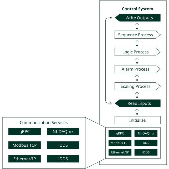
Figure 4. Communication Services
A control system reads and writes remote commands and telemetry through communication services (i.e., commanding a valve to open or starting a sequence on another remote-control system controlling a support pad). These services are daemons or microservices that run in the background, instead of executing directly inside the main application. Using a service to communicate, instead of relying on the read inputs function itself, enables the main application to monitor the metrics of the microservice so that any issue does not impact the main application’s execution. This abstracts the communication away from the main control loop, making it easier to update equipment and configurations over time as new devices with new communication interfaces become available.
A few examples of communication services are listed in Figure 4, but there are many options for communications. The facility design team may establish a custom communication protocol for the facility, or they may select standard protocols that support the equipment used across the facility.
When purchasing new equipment, a key factor will be support for existing communication services at the facility. Controlling the number of communication protocols on the site simplifies the development and maintenance of the software. Using services improves the process when a new communication protocol is allowed.
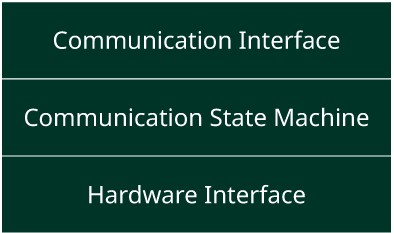
Figure 5. Communication Service Design Pattern
Each communication service will need to be designed to meet the needs of a device and protocol.
A typical communication service has some common elements. At the core of a service is a state machine, tracking the current state of the hardware determining the next desired state. For example, a device may need to be initialized before a command can be sent—the state machine tracks the initialization status of the device, requests the initialization, and then requests the command to be sent. The service provides metrics that can be monitored by the other network applications—such as when a step times out or loses communication with a device. These can prompt actions in other systems.
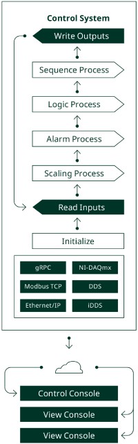
Figure 6. Operator Consoles
A hardware interface communicates with the hardware using the vendor’s API.
A communication interface packages the data for the protocol—which may include specific formatting, metadata, encryption, or compression. Some protocols require handshaking or configuration management, which is passed to the state machine for management.
To provide operator access, each control system may have an operator console or multiple consoles. To avoid confusion in the control system, there is typically only one active control console. This might be a dedicated control console or a console with control arbitration, allowing an operator to request control.
A design feature to consider is reconfigurability in the consoles. Because of changing test needs between tests, or even during a test, test engineers often need access to additional data in these consoles. Since most of the data they might need is available in the communication services, it is possible to create consoles that allow users to subscribe to new data points without changes to the actual software code. This provides flexibility to the engineers who need the data and protects the rest of the system from changes made to the software. For example, the console can subscribe to all the data channels in the communication services and let the console user select which signals to view. NI used this design pattern when creating the Static Data Viewer using NI G Web Development Software.
Similarly, designers should consider whether to expose command signals to the operator consoles in a configurable way. This allows test engineers to change control capabilities without requiring updates to the software—increasing productivity in the fast-paced rocket test environment. This capability needs to be designed into the communication service that passes the data to the control system during the read inputs step.
A console may be a dedicated device or screen for a specific control system or may be combined with other consoles into an operator station. An operator station provides view and control from a single location across the entire test stand.
Putting this together, a full architecture emerges.
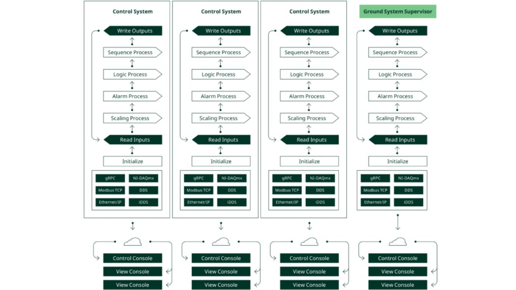
Figure 7. Rocket Test Facility Architecture
This architecture features these benefits:
- Each system runs independent of other systems, avoiding delays from waiting for another system to respond.
- As independent systems, each system can use the most appropriate technology without impacting decisions about technologies on other systems.
- The common design pattern across systems simplifies development and maintenance for both hardware and software teams.
- The architecture can grow as the facility grows, supporting any number of test stands and support systems.
- The architecture supports components from any vendor and can be updated when new technologies become available.
Finally, fully assembled, a rocket test facility may look something like the image in Figure 8:
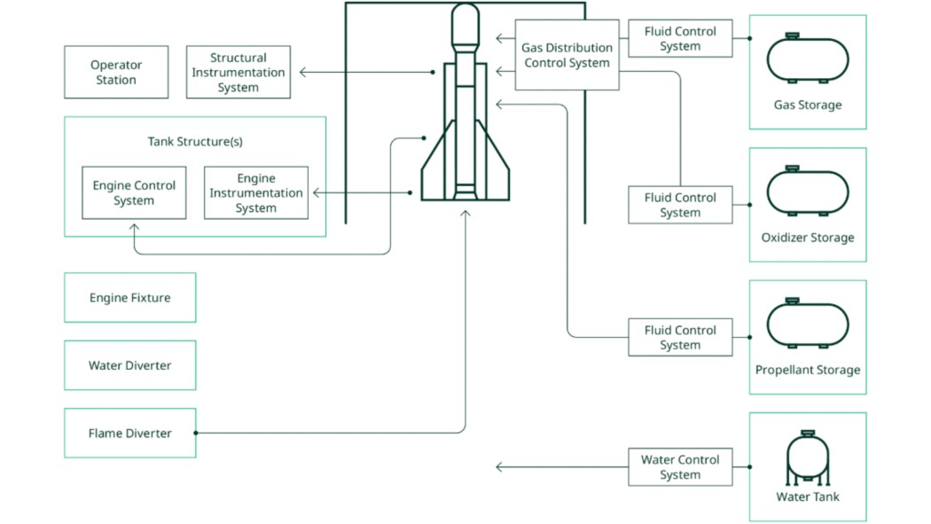
Figure 8. Rocket Test Facility
Considerations for Test Architecture Design
The architecture described in this paper provides a design pattern for the design of a rocket test system. There are many engineering decisions to make to implement this architecture. The goal of this paper is to guide a team through the aspects of the architecture to ensure that the most critical aspects are considered at the start of the design process.
When making decisions about how to implement the architecture, the following topics have proven to be some of the most critical to consider as early in the process as possible.
System Latency
Within each subsystem, and across the entire test facility, what is the worst possible delay that can be tolerated to maintain control and safety in the test area?
Latency across the system is the result of several design decisions. Faster loops will increase the communication speed from one component in one system to another component in another system. But engineers must also consider the number of hops between systems—if data must be passed among several systems to reach the final target, the cumulative delays will be more than if data can be passed more directly between control systems. When making design decisions, consider how data is made available to other systems—directly, or by being copied multiple times among the systems.
Timing
Systems spread across the facility will have differing time clocks. What amount of time skew can you tolerate across your measurements?
Most systems tag measurements with the system clock from the local device. When analyzing data across systems, it is helpful to be able to correlate the data across these systems. A common solution is to provide an absolute time across all the systems, using IEEE-1588 or a similar protocol. The time may be provided by the facility supervisor system, or systems may rely on a GPS signal for the timebase.
A related consideration is how to correlate the data between the process computer and the ground system. In a rocket test this is fairly straightforward, but in a launch situation this becomes more complicated because any links between the ground system and the rocket will be lost at launch. Since test systems replicate launch conditions, this should be considered when designing the test stand.
Distribution of Shared Resources
Which subsystems will be shared among test stands, and which subsystems will be dedicated to a specific test stand?
There are two costs to balance when considering shared resources—the costs of duplicating resources and the costs of sharing resources. There is a significant cost to set up a cryogenic tank system. But running cryogenic fluids to two separate test stands also incurs a significant cost and complexity. Sharing resources may also limit the ability to run two activities in parallel if they both require the resource to run.
Managing Race Conditions
How will shared resources be protected from competing instructions from control systems?
Any control system that can be controlled by multiple command systems runs the risk of performing an unintended action because of a lack of discipline in the communication system. For example, a valve may start an operation based on a request from a test stand, but if a second test stand overwrites the set point the result be a catastrophic failure in both stands.
The design team must carefully review the system for potential race conditions to ensure that there is a proper lockout procedure for any command signal in the system.
Race conditions can also affect measurement data if data is overwritten before a storage system retrieves the data—the data being retrieved may not be the intended data.
Redundancy
What systems must have redundant controls in place? What level of redundancy will be in place?
Redundancy can be applied at many places within a system—there can be redundant sensors, wiring, acquisition devices, processors, algorithms, or power supplies. Some space companies require triple redundancy throughout the system for maximum safety. Others identify the highest-risk failure points and focus redundancy efforts on those failure points.
There are several models of redundancy the design team can choose from for each point in the system. In standby redundancy, an identical secondary unit backs up the primary unit. In a cold standby system, the secondary unit is idle, operating only when a watchdog identifies that the primary unit has failed. In a hot standby system, the secondary unit is powered up and actively monitoring the system, but its outputs are not used until a watchdog switches control to it. This can shorten downtime in a failure but does not preserve the reliability of the secondary unit since it is in active operation.
Modular redundancy is similar to the hot standby approach, but both systems run in parallel, and both generate outputs for the system. A voting system, sometimes called an auctioneer or voter, decides which outputs should be used. This provides bumpless transfers in the event of a failure of one of the controllers. This model can be extended beyond two controllers to multiple controllers. These and other examples are discussed in the NI white paper on Redundant System Basic Concepts.
Environmental Requirements
What environments will the measurement equipment be subjected to? What additional infrastructure do we need to protect the measurement and control equipment?
During a propulsion test, equipment on or near the stand will be subject to extreme environmental conditions. These may include sudden shocks, continuous vibration, and high temperatures.
Between tests, equipment will also be subject to environmental extremes. Hot or cold temperatures, humidity, and salt spray are all specific threats to the availability of the equipment for a test.
Engineers must be aware of the environmental conditions of the test stand. With that information, they must select or design equipment that exceeds the potential requirements of the system. This may require that they buy ruggedized equipment, add protection like conformal coating, or protect the equipment in a cabinet or an environmentally controlled outbuilding.
Network Topology
What network technologies will provide the optimum performance for data transfer on the network, including redundancy in case of a component failure?
There are many options available when designing a network topology. A successful facility topology will require detailed conversations between the IT infrastructure team and the test engineering teams. Test teams will need to describe data bandwidth, latency, and technology needs. The IT team will need to understand encryption, layout, and redundancy to plan the network layout.
Among the decisions in designing the network, the design team must decide on a redundancy model—which may include running redundant network cables throughout the facility, using rapid spanning tree protocol (RSTP), and using multiple distribution switches.
I/O Coverage
What signals do we need to measure or control?
One of the first tasks the engineering team faces is collecting a list of the signals that need to be measured or controlled in the test stand. While documenting signals, they need to list the signal type, location, resolution, data rate, excitation needs, safety needs, and voltage and current levels.
With this information, engineers can collect the signals into measurement banks, and then select the right hardware to provide access to all the signals.
Data Bandwidth
Can the network topology handle the amount of data expected during a test?
The design of the network—including computing devices, switch hardware, and subnetwork architecture—establishes the limit to the amount of data that can be moved across the network. The design team must carefully review the components of the network, looking for any bottlenecks in the system.
A theoretical calculation can provide guidance to a system design, but network applications never achieve full theoretical data rates. Data overhead and latencies impact the total throughput on the network. In designing a network, it is advisable to keep data rates significantly below the theoretical limit.
Safety
What safety systems will be required to be in place?
A rocket facility has many dangerous conditions. A mistake in the design, implementation, or operation of the systems may result in a catastrophic accident. The design team must be aware of safety protocols required by federal and local laws. The design team must also consider how to protect the personnel, equipment, and area associated with the test station in ways that are not covered by laws.
Some of the areas at a rocket facility are hazardous zones because of the gases used to power the rocket engine. Some of these gases cannot be fully contained, creating a zone where any electrical spark can result in a fire or explosion. To prevent this situation, any equipment in the hazardous area must be intrinsically safe—that is, incapable of generating a spark. This can be managed by moving electrical equipment outside of the hazardous zone. An electrically controlled valve can be placed outside the zone, so that the only equipment in the zone is the pipe leading away from the valve.
If a device must be located inside the hazardous zone, the equipment must be certified as intrinsically safe by the equipment vendor. In the U.S. this means Class 1 Div 1 certification. In Europe, this means ATEX certification based on the gas type.
If a device is outside the hazardous zone, but runs a signal into it, the device must have an intrinsic barrier to prevent a spark generated in the device from being passed into the zone. Even low-level devices, like thermocouple measurement instruments, require an intrinsic barrier to prevent power from the device (like an attached power supply) from passing into the zone. An intrinsic barrier can be attached into the signal path between the device and the hazardous zone and provides protection against both voltage and current spikes. Note that intrinsic barriers vary based on the signal type, so a barrier designed for a thermocouple would not be appropriate for a valve controller.
Certifications
What certifications need to be met by the facility, support systems, and test stand?
Different certifications are required for different areas based on populations, the purpose of the facility, local laws, and the purpose of the rocket equipment. For example, a rocket test performed on a U.S. Air Force Base may require AFSPCMAN 91-7108 certification prior to any rocket activity.
In addition to certifications required to perform the test, certifications impact the goal of the testing. If the purpose of the testing is to certify the rocket engine for use, the test stand design must meet the demands of that certification. For example, MIL-STD-8109 ensures that the device being tested meets the expected conditions of the use of the product. MIL-STD-20210 ensures that components under 300 lbs. meet the electrical and environmental requirements of a demanding application. These may be required if the U.S. Department of Defense is an intended customer of the technology being tested.
Implementation Steps
Designing a rocket test facility, with the test stand and support systems, is a large and detail-oriented project. The purpose of this paper is to provide a general design pattern and approach to the design process. It is outside the scope of this paper to outline every step in the process, but the design process will follow these basic steps. If this process is beyond the capabilities of your design team, refer to the following services section for information on how to engage NI and NI’s partners in the design process.
Identify Systems
Output: Block diagram of systems and subsystems that will be designed into the facility
Start by laying out the facility systems. Using the current and future needs of the facility, plan test stand and supporting system locations. Plan for transfer between the systems and connections among them. Decide which support systems will be shared and which will be dedicated to the test stand.
Create System Requirements
Output: Detailed requirements for each system and subsystem to be designed in the facility
For each of the identified systems, document the requirements. List the expected inputs and outputs, including update rates and communication protocol. Document the expected functionality of the system including required performance. Decide which functional team in the company will be responsible for designing each of the systems.
Identify Facility-Wide Requirements
Output: Detailed requirements of the systems and infrastructure that will tie the facility together
Using the system requirements, identify the required performance of the facility system to support those systems. Document the update rate necessary to meet the latency requirements of all the systems and components. Work with the IT team to outline the network infrastructure requirements to meet the systems’ needs. Calculate the data rates of the worst-case scenarios in the system.
Select Technologies
Output: List of technologies covering the system and facility requirements
Using the system and facility requirements, identify the specific technologies that will be acquired or developed to meet the documented needs. Meet with vendors to identify off-the-shelf technologies that can be used. Work with engineering teams to identify a custom engineering approach for remaining gaps in the systems. Where possible, test the performance of the systems to ensure they meet the requirements.
Design Communication Services
Output: Document the requirements and implementation of each of the communication services to be used for the systems and facility equipment
With a good understanding of the technologies available for the systems, document the needs of each of the communication services. Identify the inputs, outputs, and processing of each of the services. Identify the expertise needed to fully implement the services.
Design the System Controllers
Output: Design documents for each of the system controllers in the facility
Apply the system requirements to the technologies selected for the systems and facility. Document the desired inputs, outputs, and functionality with specific performance criteria. Identify the expertise needed to implement the system controllers.
Implement System Controllers and Communication Services
Output: Code running on each of the system controllers and between systems
Develop the code running on each of the system controllers and in each communication service. Document any changes from the requirements documents and verify that changes do not have impacts to other systems. Apply proper engineering principles to the development—including unit testing to verify that each component meets the documented requirements.
Connect System Controllers
Output: Values updates among control systems
Connect the system controllers and communications services. Verify that the systems work properly and within expected performance boundaries. Continue to run unit testing on components, subsystems, and systems as they get connected.
Validate System Performance
Output: Validation of the performance of each system component, system, and interconnected systems
With the full system in place, perform full validation testing of the systems and the overall system. Review the requirements to verify that all requirements are met. Report any unexpected behaviors to developers and iterate until the desired performance is obtained.
Create Operator Stations and Viewers
Output: Operator screens and stations to control and view the systems
Operator consoles will be developed along with the systems; apply usability improvements to the consoles and create the final operator consoles.
Emerging Technologies for Rocket Engine Test
There are several recent advances in available technology that can be used in this rocket test architecture.
gRPC
gRPC is an open source, high-performance framework that can run in any environment. Developed by Google and based on remote procedure call (RPC), gRPC has grown rapidly in popularity in the last five years as a way to pass data among parts of a system. Using gRPC, a client application can directly call a method on a server application on a different machine as if it were a local object. This simplifies the creation of a distributed architecture like the rocket test architecture. NI software and hardware tools work with gRPC. Get information on gRPC Support Resources & Compatibility.
iDDS
iDDS is a data abstraction protocol developed for jet turbine engine test by Rolls Royce and MDS Aero. It provides a communication service to collect data from instrument nodes, which becomes available to subscribers on the network. iDDS is built on the data distribution service (DDS) backbone and Object Management Group (OMG) standard. iDDS defines the packaging of instrumentation data on the DDS network, including measurement data like channel metadata, time stamping, configuration, and health monitoring. Because the communication among devices is standardized within the iDDS model, specific vendor features are abstracted away, making it easier to swap out equipment when new technology becomes available, even if it is from a new vendor.
Tailored NI Solutions for Advanced Rocket Engine Testing
NI provides tailored hardware and software solutions for rocket engine testing, integrating changing safety requirements, new sensors, and market-demanded technologies. Our software provides tools for custom test solutions, real-time data visualization, logging, and automated test sequencing. These software solutions enhance data analysis, facility management, and overall test efficiency through powerful, adaptable platforms.
Hardware platforms, such as NI PXI, NI CompactDAQ, and NI CompactRIO, are designed to withstand extreme conditions and support a wide range of signals, ensuring reliable and precise measurement and control during rocket engine tests. These rugged, modular systems provide distributed measurements and local processing capabilities, enhancing test accuracy and flexibility. Explore our solutions to test rocket engine propulsion to see how to test more engines on a shorter timeline than ever before.
Next Steps
Footnotes and References
Footnotes:
1 https://arstechnica.com/science/2022/01/thanks-to-china-and-spacex-the-world-set-an-orbital-launch-record-in-2021
2 https://www.go-astronomy.com/space-ports.php
3 https://www.ecfr.gov/current/title-14/chapter-III
4 https://ntrs.nasa.gov/api/citations/20050182932/downloads/20050182932.pdf
References
An NI Partner is a business entity independent from NI and has no agency or joint-venture relationship and does not form part of any business associations with NI.