NI Switch Health Center
Overview
To simplify relay maintenance and reliability in high-channel-count systems, all NI SwitchBlock modules and some PXI switch modules are shipped with the NI Switch Health Center. The NI Switch Health Center includes an integrated relay test and provides access to the relay-count tracking data stored on the NI switch hardware. Furthermore, board temperatures are reported for some switch modules. Results from the relay test are graphically displayed on a relay card diagram, making it easy to locate relays that you need to replace. Use the relay-count information to identify relays being overused because of inefficient test code as well as relatively unused relays that you could apply to extend the life of your relay cards. Finally, the NI Switch Health Center can generate HTML reports to document the results of the relay test and cycle counts for each relay in your NI SwitchBlock.
This paper is part of the Getting Started with the NI SwitchBlock series.
Download the entire Getting Started with the NI SwitchBlock white paper series
Contents
- Integrated Relay Test
- Report Generation
- Relay Replacement
- Relay Count Tracking
- Preventive Relay Maintenance
- Detecting Inefficient Switching Code
- Balancing Relay Utilization
- Temperature Monitoring
- Resistive Relay Test
- Related Links
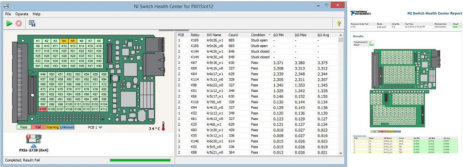
Figure 1. The NI Switch Health Center shows a completed relay test and the resulting HTML report.
Integrated Relay Test
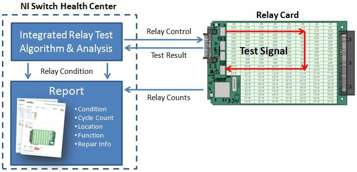
Switch modules are tested by sending a signal through a combination of routes on each card to verify the condition of each relay. When the test has finished, each relay is determined to be functional, stuck open, stuck closed, or unverified due to failures on the board that prevent the relay from being tested. After functional tests are complete, certain switch modules undergo further testing where each relay is tested for changes in resistance, returning a warning for any relays with a large change in resistance. Test results are overlaid on a relay card diagram and listed in a table with the software topology location, so that you can physically locate relays needing replacement and identify routes that may be affected.
Figure 2. The integrated relay test provides both the physical location and software topology location for failing relays.
To prevent signals used in the relay test from unintentionally connecting to external circuitry, the NI Switch Health Center requires that any cables or interchangeable test interfaces (ITAs) be disconnected from the NI switch module. For NI SwitchBlock, safety interlock circuitry prevents the relay test from running until all external connections have been disconnected. This same circuitry is also used to disconnect relay cards from the analog bus when the front connectors are exposed, making the relay cards finger safe.
Figure 3. The NI Switch Health Center is a one-stop shop for relay cycle counts and integrated relay testing.
Report Generation
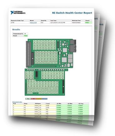
At the end of each relay test, you are given the option to generate a report documenting the condition of all the relays on each relay card along with their cycle counts. The report is created in HTML and includes links that take you online to the model page for each relay card in your system. Hardware diagrams for each relay card are also included to identify the physical location of relays needing replacement.
Figure 4. Generate and store HTML reports to track relay health over time.
Relay Replacement
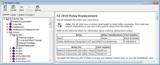
Most NI switch modules offer field replacement options for relays that have reached the end of their lifetime or have been found to be shorted or stuck open. The NI Switches Help includes a topic heading of "Relay Replacement" for each relay card with relay manufacturer information as well as instructions on how to replace a relay. After completing the replacement procedure, you can refer to the Resetting a Relay Count topic to track the lifetime of the new relay.
For example, you can find detailed instructions for replacing the relays on the NI 2810, along with the relay manufacturer and part number information, in the NI Switches Help file, as seen in Figure 5.
Figure 5. The NI Switches Help includes a section on relay replacement for each NI switch module.
Relay replacement kits for NI switch modules typically contain 10 relays.
Note: Should a heavily used relay need to be replaced while the unit is still under warranty, following the instructions in the Help document and correctly replacing the relay yourself does not affect the warranty.
If most of the relays on one of the relay cards need to be replaced at the same time or if one of the boards is damaged, you can contact support at ni.com and arrange to send the entire relay card back to NI for replacement. This can often be cheaper than buying a whole new module.
Relay Count Tracking
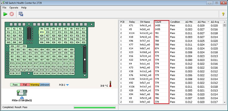
Because mechanical relays have a finite lifetime, maintaining an accurate count of relay cycles is important to ensure test system reliability. NI switch modules offer onboard relay count tracking, which you can view in the NI Switch Health Center or NI-SWITCH Soft Front Panel, or through the NI-SWITCH driver. Relay counts are stored on the switch hardware, making it easy to monitor relay actuation if hardware is moved between systems. Using this information, you can perform preventive relay maintenance, detect inefficient switching code, and, in some applications, extend the life of your relay card by balancing the relay utilization across the board.
Figure 6. The NI Switch Health Center displays relay cycle counts for long-term reliability.
Preventive Relay Maintenance
When selecting a relay for an application, an important characteristic to consider is its life expectancy, which is usually specified in relay cycles. One cycle is defined as the action of opening and closing the relay. Most switching products provide both mechanical and electrical expected lifetimes.
The mechanical lifetime is the typical number of cycles that a relay can sustain under dry switching conditions (switched with no electrical load) and is based on metal fatigue within the bending armature or reed switch. This number tends to be several orders of magnitude above the electrical lifetime and is rarely reached in switching systems.
Switching active electrical signals, especially high-power signals, causes arcing across the relay contacts. This arcing produces pits on the contact surface and accelerates the contact wear. The electrical life specification is the number of switch cycles, under load, before the contact resistance rises above a certain value, or, in the case of reed relays, the reed switch contacts weld closes. This electrical life specification is often used as the cycle limit for a given relay; however, it cannot be used as a leading indicator for relay failure unless the load being switched in your test system matches the load that was used to determine the relay specification.
You can use relay count tracking to determine a more accurate life expectancy for each of your relays and their respective loads. In addition, if monitored, tracking can be used to anticipate relay failures over time. You can read this information from the hardware at any time using the NI-SWITCH driver and integrate it into your test code to supply operator warnings if relays exceed their electrical life expectancy.
Detecting Inefficient Switching Code
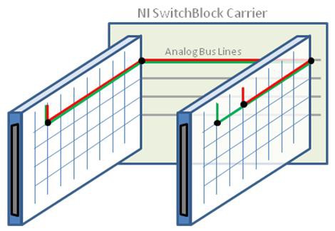
Over time, you might notice large discrepancies between relay counts caused by inefficient switching code. For example, if you connect a signal from a column on relay card 1 to a column on relay card 2 using analog bus 0, you need to close the relays for each column to the first row on each card and then close the analog bus relays on each card to connect to analog bus 0 (see the red route in Figure 4). If you then want to connect from the same column on relay card 1 to a different column on relay card 2, the most efficient way to make the connection is to simply change the row to column relay on relay card B and leave the remaining three relays closed (see the green route in Figure 4). However, if your software disconnects all four relays before connecting the second route, then three of the four relays cycle unnecessarily.
Figure 7. Three of the four relays are shared for both the red route and the green route. Keeping these relays closed when switching from red to green minimizes relay cycles.
To optimize your switch code, the NI Switch Executive API includes the Connect and Disconnect VI, which examines both paths and leaves relays common to both routes closed to minimize relay actuation. Alternatively, you can resolve some of these issues by closing the overused relays for the duration of the test using Multiconnect Mode.
Balancing Relay Utilization
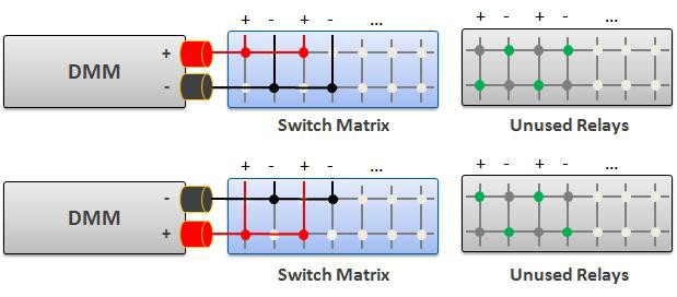
When differential signals are routed through 1-wire matrices, nearly half of the relays are left unused, as shown in Figure 5. You can verify this type of relay utilization through relay count tracking and balance it with changes in software and minor changes in wiring for switching that uses row-column signal routing.
Figure 8. Switching differential signals often results in unused relays. Swapping the HI and the LO of the DMM and making some small changes in software balances relay utilization.
Figure 9. In systems that use column-to-column signal routing, you can balance relay utilization for differential signals without changing external wiring.
Temperature Monitoring
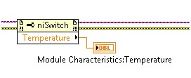
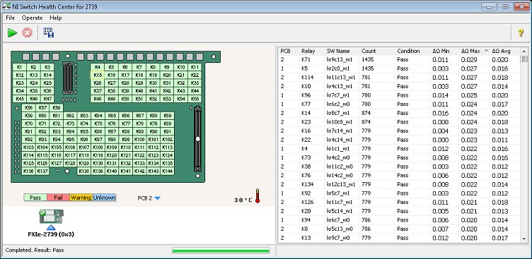
Because temperature can impact resistance levels and data readings, monitoring module temperature allows users to better understand and account for their testing conditions. Some NI PXI switch modules have onboard temperature sensors that report temperature readings, which you can view in the NI Switch Health Center or NI-SWITCH Soft Front Panel, or through the NI-SWITCH driver.
Figure 10. The NI-SWITCH driver provides access to board temperature via niSwitch property node
Resistive Relay Test
Some NI PXI switch modules include integrated resistive relay tests, an additional Switch Health Center feature, which is capable of checking for changes in relay resistances. Large changes in contact resistance over time can indicate that a relay is approaching, or has reached, end-of-life. The NI Switch Health Center tests for changes in resistance using the integrated relay resistance test. When you run a relay test with the NI Switch Health Center, you can view the resistance change across individual relays to determine whether a relay is nearing the end of its usable life. For each relay, multiple resistance measurements are taken and reported, including the minimum, maximum, and average resistance change. The integrated relay resistance test reports the change in resistance relative to a baseline resistance measured at the time the device was manufactured. A large change in resistance from the baseline indicates that the relay will soon need to be replaced.
Figure 11. The NI Switch Health Center displays board temperature and changes in relay resistance.
