7 Tips for Optimizing Your Source Measurement Unit
Overview
Source measurement units (SMU) are gaining popularity due to their ability to consolidate the functionality of a programmable power supply, programmable load, and DMM in a single instrument. However, most engineers have only scratched the surface on the impact that an SMU can make on their test system performance and throughput. With the ultimate goal of reducing both cost and test time, the following seven tips will have you on your way to characterizing and validating your products faster and more economically.
Contents
- Monitor Your Startup Voltage with an Oscilloscope
- Evaluate Price Per Channel and Measurement Time
- Create Custom Output Signals for Advanced Characterization
- Adopt Hardware-Timed Sequences
- Use Self-Calibrate to Improve Measurement Repeatability
- Account for Voltage Drop with Remote Sense
- Customize Your SMU’s Transient Response for Each Device Under Test
- Related Links
Monitor Your Startup Voltage with an Oscilloscope
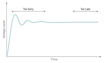
Measuring before your SMU has settled will cause uncertainty in test results, but waiting too long is a waste of precious time. Use an oscilloscope or digitizer to probe the output levels of your SMU while connected to your device under test (DUT) to ensure that you are not waiting too little or too long to take a measurement with your SMU.
Figure 1. Probe the voltage output lines of your SMU to optimize your measurement quality and time.
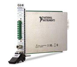
Traditionally, an external oscilloscope with voltage and current probes is required to view the output of an SMU. The PXIe-4139 Precision System SMU has an integrated 1.8 MS/s digitizer that removes the need for both an external oscilloscope and external cabling – you can probe the output power directly from the internal channels. In addition, the digitizer can be used to troubleshoot if you notice any noisy power rails during a test.
Figure 2. The PXIe-4139 Precision System SMU has an integrated digitizer to simplify the process of monitoring output power levels during characterization and validation.
Evaluate Price Per Channel and Measurement Time
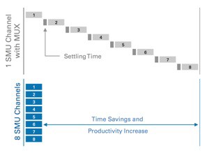
A common approach to solving high-channel count test requirements is to add a switch or multiplexer between the SMU and devices under test. While economical, this serializes measurements and can greatly reduce productivity as you must wait for the switch to settle.
Figure 3. Increasing SMU channels for high channel count applications increases productivity and greatly reduces measurement time.
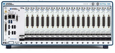
Recent improvements in the channel density of modular SMUs has greatly driven down the price per channel of SMU systems. An 18-slot PXI Chassis such as the PXIe-1085 24 GB/s chassis can be filled with 4-channel SMUs such as the PXIe-4141 Precision SMU to create a 68-channel system that fits within a 19-inch test instrumentation rack. Due to the PXI architecture, all SMUs share the same CPU, triggering lines, and power supply to help keep down not only capital costs, but also floor space costs in the production environment.
Figure 4. High-density PXI SMUs enable systems with up to 68 SMU channels in a single 4U rack size.
Create Custom Output Signals for Advanced Characterization
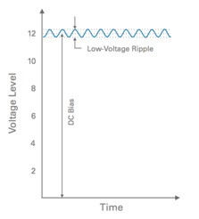
Radio Frequency and Power Management ICs often require advanced testing approaches to ensure the device is functioning as expected. An example of this complexity is testing the power supply rejection ratio (PSRR) of a linear regulator. This requires superimposing a low-voltage AC ripple on top of a DC bias to ensure that the regulator can effectively block this AC ripple on the output.
Figure 5. The input signal used to characterize the PSRR of a linear regulator consists of a low-voltage
AC ripple superimposed on top of a DC bias.
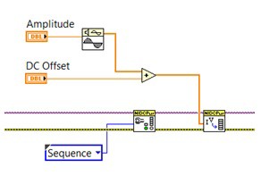
With a traditional SMU, you must use an external AC source and external filtering circuitry to ensure that you do not damage your SMU. Because modular SMUs are software-defined and have the option for hardware-timed sequences, you can create a custom waveform in software to output the DC biased AC signal. The PXIe-4139 Precision System SMU has a hardware-timed update rate of 100 kS/s, which provides a smooth AC signal under 1 kHz.
Figure 6. Modular SMUs such as the PXIe-4139 Precision System SMU can be programmed with software such as LabVIEW to output a custom waveform for advanced test requirements.
Adopt Hardware-Timed Sequences
Software-timed sequences are a great way to get up and running quickly when automating measurements from an SMU. However, they can wreak havoc on your test system’s determinism when software jitter becomes a factor during time-sensitive sequences. As an added speed advantage, this approach removes the communication latency between the host computer and instrument between each measurement. Hardware-timed sequences allow you to change various parameters of the SMU such as output mode, aperture time, current range, transient response, at each step.
Figure 7. Software-timed sequences (grey) run irregularly compared to the deterministic execution of hardware-timed sequences (blue).
For more information about hardware-timed sequencing, refer to the Measurement and Update Timing Characteristics section of the NI PXIe-4139 Device Specifications. As an added bonus, NI SMUs have the ability to send ‘Source Complete,’ ‘Measure Complete,’ and ‘Sequence Complete’ triggers to other instruments to synchronize measurements in advanced test systems.
Use Self-Calibrate to Improve Measurement Repeatability
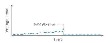
The calibration cycle for most instruments is between one and two years, leaving many days in-between that your instrument can slowly drift from the calibrated point. Modern SMUs feature the ability to reference the measured value of a known signal and digitally tune the instrument to calibrate for the difference. While this does not extend the calibration cycle, it does help to overcome the effect of time and temperature drift of your SMU.
Figure 8. Use the self-calibration functionality of your SMU to increase measurement reliability and repeatable by nullifying the effect of time and temperature drift.
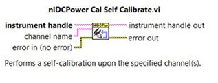
The PXIe-4139 Precision System SMU and other modular SMUs from NI can be self-calibrated manually using NI MAX, the free application for accessing and configuring your NI hardware. For increased reliability and repeatability, you can programmatically self-calibrate your SMU, as well as any NI modular instrument, during the initialization of your test sequence using a single function in LabVIEW. For more information, refer to page 6 of the NI PXIe-4139 Calibration Procedure Manual.
Figure 9. Programmatically self-calibrate your modular SMU using a single function in LabVIEW.
Account for Voltage Drop with Remote Sense
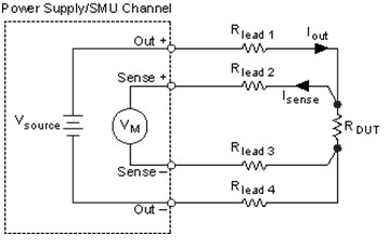
It is not always possible to minimize cabling between your SMU and DUT when stepping through constant voltage settings, resulting in a voltage drop and erroneous test data. To mitigate this effect, the traditional approaches are to mathematically calculate this drop or measure the voltage at the DUT using an external DMM. With modern SMU technology, you can use remote sense wires to perform a 4-wire measurement with the highest quality and lowest effort.
Figure 10. Use remote sense to increase SMU measurement quality.
The industry-leading modular SMU, PXIe-4139 Precision System SMU, features remote sense terminals to increase accuracy and reduce complexity of test setup. For more information, read the Remote Sense section of the NI DC Power Supplies and SMUs Help file.
Customize Your SMU’s Transient Response for Each Device Under Test
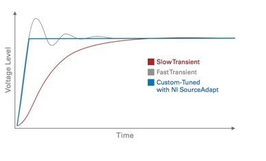
Traditional SMUs have fixed analog circuitry that configures the transient response or rise time of their power supply. This approach typically results in two settings (normal, and high-capacitance) to customize the response of the power supply for each DUT, but it is never fully optimized for the characteristics of their DUT. The NI PXIe-4139 features the patented technology, NI SourceAdapt, to digitally control the transient properties of the SMU to maximize stability, reduce overshoot, and greatly reduce test times.
Figure 11. NI SourceAdapt maximizes stability, reduces transients and reduces test times by digitally tuning the
response rate of the SMU supply.
