Benefits of Parallel Testing
Overview
Contents
- Introduction
- Choosing a Parallel Test Architecture
- Common Parallel Process Modules
- Instrument Sharing and Synchronization
- Sample Parallel Test Results
- Additional Resources
Introduction
As a test engineer, you may have explored ways to enhance test system performance in the past though parallel testing. However, the latest off-the-shelf test management software tools simplify parallel test system implementation. These tools increase test throughput and drive down test system costs.
In general, parallel testing involves testing multiple products or subcomponents simultaneously. A parallel test station typically shares a set of test equipment across multiple test sockets, but, in some cases, it may have a separate set of hardware for each unit under test (UUT). The majority of nonparallel test systems test only one product or subcomponent at a time, leaving expensive test hardware idle more than 50 percent of the test time. Thus, with parallel testing, you can increase the throughput of manufacturing test systems without spending a lot of money to duplicate and configure additional test systems.
The following sections discuss ways parallel testing can reduce the cost of test and describe various approaches for implementing parallel testing in your test systems. Advances in parallel testing offer a great solution to avoid replicating test systems by delivering increased test throughput, increased coverage, and reduced test cost.
Choosing a Parallel Test Architecture
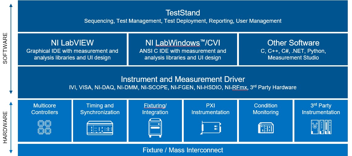
While you can implement parallel testing in most existing test systems, modular test system architectures deliver the best results when used in a parallel testing environment. Test management software, such as TestStand, and modular PXI hardware components offer many features for obtaining the highest performance out of a parallel test system. However, you can implement parallel testing using much of your existing test hardware without further hardware investment. Once you have selected your test architecture, the next step is to select the best process model based on your desired UUT test behavior. Figure 1 illustrates a modular test architecture by showing how one can modularize test management services, test modules, measurement services, and test hardware.
Figure 1. Modular Test System Architecture
Common Parallel Process Modules
When testing the proper assembly or functionality of a UUT, there are a variety of tasks to perform in any test system. These tasks include a mix of model or family-specific tests as well as many procedures that have nothing to do with actually testing the UUT. A process model separates the system-level tasks from the UUT-specific tests to significantly reduce development efforts and increase code reuse. Some of the tasks that a process model handles are tracking the UUT identification number, initializing instruments, launching test executions, collecting test results, creating test reports, and logging test results to a database. TestStand provides two process models – the parallel process model and the batch process model – to facilitate the general test flow of parallel testing based on your UUT test requirements.
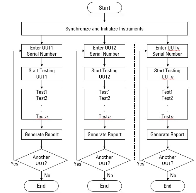
You can use a parallel process model to test multiple independent test sockets. With this model, you can start and stop testing on any UUT at any time. For example, you might have five test sockets for performing radio board tests. Using the parallel process model, you can load a new board into an open socket while the other sockets test other boards. Figure 2 illustrates how the Parallel Process executes.
Figure 2. Parallel Process Model Flow Chart
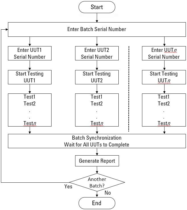
Alternatively, you can use a batch process model to control a set of test sockets that test multiple UUTs as a group. For example, you might have a set of circuit boards attached to a common carrier. The batch model ensures you can start and finish testing all boards at the same time. The batch model also provides batch synchronization features. For instance, you can specify that the step runs only once per batch if a particular step applies to the batch as a whole. With a batch process model, you can also specify that certain steps or groups of steps cannot run on more than one UUT at a time or that certain steps must run on all UUTs simultaneously. Refer to Figure 3 to see an illustration of how the Batch Process Model is accomplished.
Figure 3. Batch Process Model Flow Chart
Instrument Sharing and Synchronization
If you are trying to increase your test system performance while lowering your cost, providing each test socket with a dedicated set of instruments is not a feasible solution. Implementing a parallel test system often does not require any additional hardware investment. With parallel testing, you can share existing instrumentation in the test system among multiple test sockets. Decreasing idle time during a UUT test cycle provides substantial performance improvements without additional hardware costs. In many cases, you can add additional inexpensive instruments to further optimize overall system performance while sharing the more expensive hardware among the test sockets.
Prior to the availability of off-the-shelf test management software, programming the allocation of shared instrumentation among multiple test sockets running in a parallel test system required that you add a large amount of low-level synchronization code to test programs. Critical sections and mutexes often were intertwined with the actual code, making it difficult to program or reuse sections in future test systems.
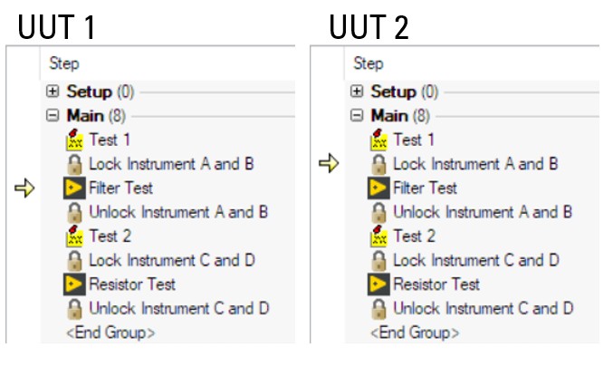
By implementing parallel test systems that take advantage of many of the built-in features in TestStand, you can effortlessly control the sharing of instruments and synchronize multiple devices under test. You can use synchronization step types and configurable test properties at the individual test level to manage resource sharing between tests in a sequence. The synchronization step types used in test sequences often include lock, rendezvous, queue, notification, wait, and batch synchronization step types. Figure 4 shows how a lock step can be used while testing two UUTs.
Figure 4. Example test sequence uses a combination of lock step types to prevent multiple tests from trying to access the same instrument simultaneously.
You can also use configurable instrument-sharing properties associated with a specific test step rather than a group of tests. Most automated test systems involve some aspect of switching or signal routing. This implementation can span from simple general-purpose relays that control power to a UUT all the way to complex matrix configurations that route thousands of test points to dozens of instruments. When the number of relays to control is small, the test code required to control them is straightforward. As the number of routes increases or spans multiple switch modules, developing software to manage this functionality can be time-consuming and costly.
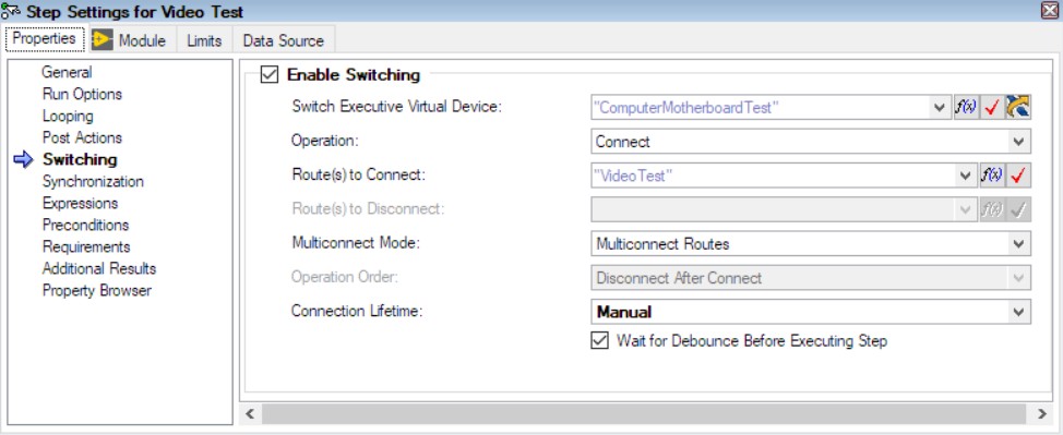
Switch Executive is an intelligent switch management and routing application. With Switch Executive, you gain increased development productivity by interactively configuring and naming switch modules, external connections, and signal routes. You also increase test code reuse and system performance with switch programming in conjunction with TestStand, LabVIEW, LabWindows/CVI, and Measurement Studio. Figure 5 shows the interaction between TestStand, Switch Executive and your hardware. Ultimately, Switch Executive simplifies switch system configuration and increases test performance, thus lowering your cost to test. For systems developed using TestStand, switch configuration can be included as a property of each test step. The switch programming in these situations is simplified by using the previous configuration of virtual devices, route/route groups in Switch Executive.
Figure 5. TestStand Window for Defining Switching Functionality Using Switch Executive
This method separates switch code from the individual test code modules in an ATE system. As switching hardware changes in the future, your instrumentation test code can stay the same in this manner. The ability to make parallel testing a modular property of tests, rather than an inseparable part of each test, eliminates the complexity of implementing parallel testing in years past.
Sample Parallel Test Results
To further illustrate the improved instrument usage rates and increased throughput of parallel testing, test results were recorded before and after applying parallel testing to a typical automated test system. The test system performs a trio of electrical component tests and frequency response tests on filters in each UUT. The test system uses TestStand and LabVIEW test software tools to create and manage the testing. The test system includes two sources, one DMM, one digitizer, one multiplexer, and one high-density switch.
Figure 6. The results from testing the UUTs sequentially in a traditional fashion.
In high-speed production environments, any improvements made to speed up throughput and reduce test times are valuable in cutting costs. Figure 6 illustrates how a traditional fashion UUT sequential testing could be accomplished. In Figure 7, we see how to improve the instrument usage rates and increase the test throughput of the tester; you can add three additional test sockets to test four UUTs in parallel, sharing the same set of hardware previously used in the sequential test.
Figure 7. Flow and performance improvements of parallel testing in this manner.
Figure 8 shows how you can apply a new parallel testing technique, called autoscheduling, to the set of tests running on the UUTs. Autoscheduling can typically improve your instrument usage rates and test throughput by an additional 10 to 15 percent over parallel testing. Using the same test configuration, autoscheduling improves the instrument usage and test throughput by eliminating a major portion of the idle time at the beginning of the test executions, by skipping tests that are waiting to acquire resources and returning to them at a later time in the test sequence. The use of autoscheduling requires that tests in an autoscheduled section be capable of executing in any order and that they be independent of prior test results.
Figure 8. Autoscheduling optimizes test system performance.
Through the use of parallel testing and autoscheduling technology, you can increase DMM and digitizer usage by nearly 40 percent and throughput by almost 50 percent compared to traditional sequential testing as depicted in Figure 9.
Figure 9. Comprehensive Test Time and Usage Rate Comparisons
Adding less expensive devices, such as DMMs or low-end digitizers alleviates constrictions in the test flow, providing true parallel measurements and maximizing both efficiency and throughput. To Learn more about parallel test architectures in TestStand, please visit Parallel Test Architectures for Reducing the Cost to Test.
