Programming Options for NI Software-Designed Instruments
Contents
- What is a Software-Designed Instrument?
- The Benefits of FPGAs in Test Applications
- NI Software-Designed Instrument Programming Options
- Choosing the Right Software Experience
- Next Steps
What is a Software-Designed Instrument?
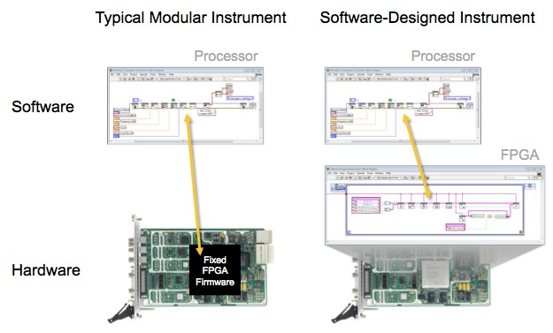
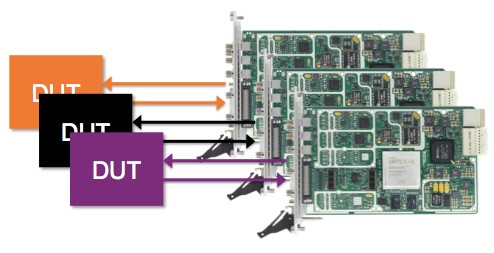
Software-designed instruments enable new levels of instrument performance not previously possible through the flexibility of user-programmable FPGAs. Compared to typical modular instruments, software-designed modular instruments share the same hardware architecture and measurement quality. They also both have instrument drivers that allow software customization on their host processors. This software-based approach, called virtual instrumentation, has become the de facto standard for developing automated test applications. Software-designed instruments take virtual instrumentation even further, providing user access to the performance of FPGA technology. NI software-designed instruments have all of the out-of-the box functionality that you would expect from an instrument, but are architected so that they can be easily extended to provide application-specific FPGA enhancements.
Figure 1. NI software-designed instruments provide the out-of-the-box functionality you expect from an instrument, with the ability to add application-specific FPGA enhancements.
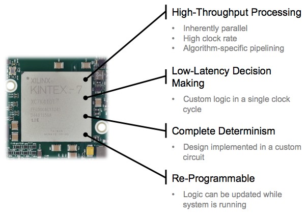
FPGAs are the ideal silicon component to serve as the brain of a modular instrument. Compared to microprocessors, they have the ability to implement higher-performance processing with guaranteed determinism and low-latency decision-making. While application-specific integrated circuits (ASICs) can achieve the same levels of performances as FPGAs, they cannot be re-programmed which means that vendors cannot add functionality over time, and more importantly, end users cannot customize the ASIC to meet their needs.
Figure 2. FPGAs provide the performance and features necessary to support modern instruments.
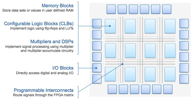
FPGAs consist of several core components, all of which are programmable. Configurable logic blocks (CLBs) and programmable interconnects implement arbitrary digital logic, and allow data to traverse the FPGA silicon. Block RAMs allow for temporary data storage during operation, and can be partitioned and allocated based on the required functionality. On-FPGA multipliers and DSP blocks provide the computational elements needed to perform high-throughput math and signal processing. Flexible I/O blocks make it possible to interface with other electronic components outside the FPGA. These include ADCs, DACs, and digital buffers for instrument I/O, clock synthesizers for synchronous instrument operation at specific rates, DRAM components for large-depth on-instrument storage, and bus interfaces for transferring measurement data to the host processor.
Figure 3. Programmable FPGA components support the needs of modern instruments.
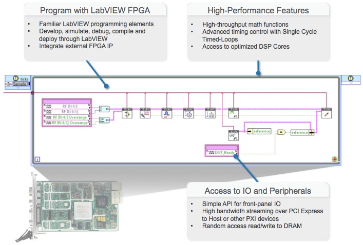
While FPGAs deliver unparalleled levels of performance, programming them with traditional languages such as VHDL is challenging. The LabVIEW FPGA Module dramatically simplifies FPGA programming for NI hardware. Familiar graphical programming enables quick design capture, minimizing time spent writing code. FPGA-specific functions such as the single-cycle timed loop, high-throughput math libraries, memory nodes, graphical clock configuration utilities, and third party IP integration nodes enhances the LabVIEW language to maximize performance on FPGA targets. Abstractions for access to instrument I/O, interfacing with on-instrument DRAM, and data movement over the bus to the processor greatly simplify these complex tasks. An integrated design flow allows you to develop, simulate, and compile FPGA code from within a single environment. The LabVIEW FPGA Compile Cloud Service provides off-site compilations on dedicated, high-performance machines, reducing the processor burden on your development machine. Finally, specific to software-designed instruments, IP libraries, including instrument design libraries, along with design templates delivered through example code provide all the capabilities you expect from an instrument, right out of the box.
Figure 4. LabVIEW FPGA dramatically simplifies FPGA programming for NI hardware.
The Benefits of FPGAs in Test Applications
The possible application-specific FPGA enhancements are limited only by the nature of the instrument I/O, but for test applications they can be divided into five broad categories. These include on-FPGA measurements and stimulus generation, closed-loop or protocol-aware test, custom triggering and data reduction, deterministic test execution and DUT control, and DUT or application-specific personalities. Each of these enhancements are ultimately designed to lower the total cost of test by delivering higher test throughput, providing hardware re-use and future-proofing, or by enabling new and innovative tests not previously possible.
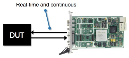
On-FPGA measurements and stimulus generation move these tasks from the host processor to the FPGA, either completely or even partially. When implemented on the processor, measurements and stimulus generation are not typically real-time, as the time to compute measurements or generate waveforms is longer than the waveforms themselves. On the FPGA these algorithms can be computed in real-time, however, so they can be executed continuously and virtually instantaneously. This might deliver higher test throughput by reducing the measurement computation time, or it might enable new types of tests by performing measurements continuously over an indefinite period or by generating long-duration non-repetitive waveforms. Examples of these types of FPGA enhancements include RF spectral measurements, digital bit error rate calculation, phase-continuous tone generation, or intentional waveform impairments such as distortion or noise.
Figure 5. On-FPGA Measurements and Stimulus Generation
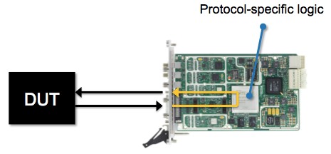
Closed-loop or protocol-aware test takes advantage of the FPGA’s determinism and low-latency decision-making to interact with the DUT in real time. This might reduce the burden on the host processor to deliver higher test throughput, it might facilitate the evolution of communication protocols to enable hardware re-use, or it might enable new types of real-time, closed-loop tests which were not previously possible. Examples of these FPGA enhancements include emulating the DUT’s real-world operating conditions such as through channel emulation or by emulating the device to which the DUT will eventually interact, or by implementing digital or RF communications protocols on the FPGA.
Figure 6. Closed-Loop or Protocol-Aware Test
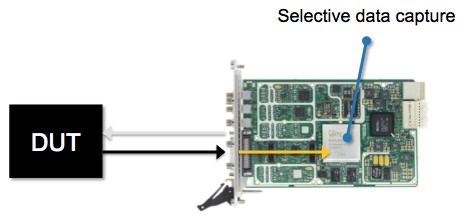
Custom triggering and data reduction aims to isolate the minimum amount of data required to make a particular measurement, reducing the amount of subsequent processing on either the FPGA or host microprocessor. This might deliver higher test throughput by reducing the measurement computation time, it might enable hardware future-proofing by allowing the addition of new instrument capabilities over time to gain additional insight into ever-evolving signals of interest, or it might enable new and innovative measurements by capturing rare events with 100% confidence. Examples of these FPGA enhancements include frequency domain triggers, real-time time domain envelope triggers, pulse triggers, and time or frequency domain decimation.
Figure 7. Custom Triggering and Data Reduction
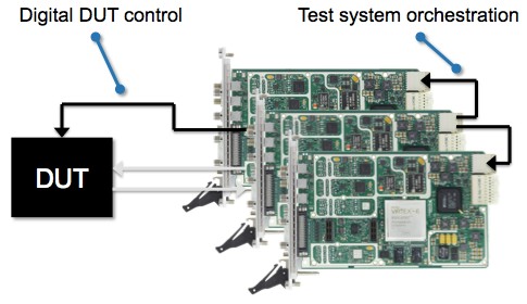
Deterministic test execution and DUT control moves the sequencing and decision-making from a software test executive into hardware logic, where it runs as fast as possible with complete determinism. DUT control typically involves communicating with the device under test through some type of digital protocol in order to change its operating mode over the course of the test sequence, if necessary. An FPGA-based state machine can then replace the software test executive and control the software-designed instrument signal generation and/or acquisition, the digital DUT control, and even other instruments in a PXI system through the backplane trigger lines. This type of FPGA enhancement is purely designed to deliver higher test throughput in very high volume automated test applications where the savings of even milliseconds is very valuable. Examples of digital DUT control protocols include I2C, SPI, JTAG, and RFFE, and hardware test sequencer and DUT instruction sequencer IP facilitate hardware-based test execution.
Figure 8. Deterministic Test Execution and DUT Control
DUT or Application-Specific Personalities combine the various FPGA enhancements described above to deliver FPGA features optimized for specific devices under test. Theses personalities can be reconfigured over the course of testing a single device, or they may be swapped when an instrument is re-purposed for testing a different device. The former scenario might occur when a single software-designed instrument is performing the function of several traditional instruments. The latter scenario might occur frequently in a high-mix testing environment where many devices share a common assembly line, or less often in high-volume environments when hardware is reused after the prior device is at the end of its life and is no longer in production. Regardless, the benefit is hardware re-use, cutting down on capital cost. An example of this kind of FPGA enhancement is updating the digital protocol in a protocol-aware test as new features or increased performance are added to the protocol specification.
Figure 9. DUT or Application-Specific Personalities
NI Software-Designed Instrument Programming Options
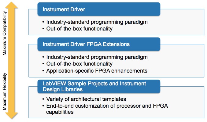
NI software-designed instruments feature multiple programming options, and the optimal one depends on the demands of the particular application. For maximum compatibility with existing test code and testing paradigms, instrument drivers deliver industry-standard APIs that meets these needs. For maximum flexibility, NI instrument design libraries and LabVIEW Sample Projects provide lower-level building blocks and architectural templates that you can completely customize. Instrument driver FPGA extensions provide a “best of both worlds” approach that delivers the same industry-standard APIs, but also allows the addition of application-specific FPGA enhancements.
Figure 10. Software-Designed Instrument Programming Options
NI instrument drivers deliver hardware abstraction based on the specific type of instrument. For instance, the NI-Scope instrument driver supports all NI modular oscilloscope hardware products. These drivers enable code portability across driver versions, hardware devices, and even other vendors through the support of interchangeable virtual instruments (IVI). They offer host APIs in LabVIEW, as well as C/C++ and .NET. Additionally, they provide device configuration in the NI Measurement and Automation Explorer (MAX), interactive use through soft font panels (SFPs), example programs that demonstrate the full functionality of the API and hardware, and integrated help and documentation.
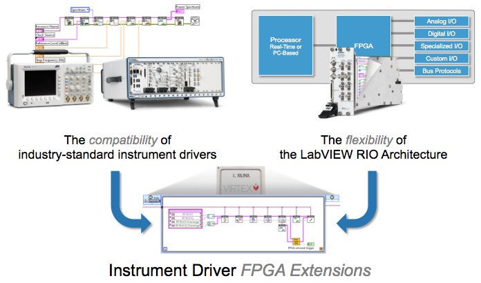
Instrument driver FPGA extensions build on the capabilities of NI instrument drivers by enabling application-specific FPGA enhancements. When using a custom instrument FPGA personality, known as a bitstream or bitfile, the instrument driver works in the same way as with the NI-supplied default personality, and you have additional control over the additional FPGA functionality through the lower-level NI-RIO API.
Figure 11. Instrument Driver FPGA Extensions
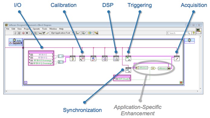
You can download pre-built custom FPGA personalities from ni.com, or obtain them from select NI alliance partners. You can also build your own with the LabVIEW FPGA Module, currently through an early access program (ni.com/beta). When building your own, you start with the same code used to build the default FPGA personality with all the necessary IP. You can then add your own application-specific modifications and additional IP.
Figure 12. Instrument driver FPGA extensions deliver the core functionality of a software-designed instrument while enabling application-specific FPGA enhancements.
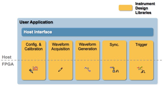
For more substantial FPGA modification, the NI instrument design libraries deliver the low-level building blocks of an instrument as disaggregate host and FPGA code modules. This disaggregation enables simplified removal or addition of these components to a given design, maximizing the functionality of limited FPGA resources and delivers architectural flexibility.
Figure 13. NI Instrument Design Libraries
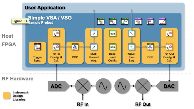
In addition to the instrument design libraries, NI provides LabVIEW sample projects that serve as architectural templates optimized for different applications. These sample projects deliver a namespaced copy of the host and FPGA code intended for user modification.
Figure 14. LabVIEW sample projects are built on top of instrument design libraries and deliver starting points for a variety of applications. This image depicts a record-based acquisition and generation architecture for NI Vector Signal Transceivers. The code in blue is intended for user modification.
Choosing the Right Software Experience
To get up and running quickly with a new software-designed instrument, NI instrument drivers deliver the best out-of-the box experience with the fastest time to first measurement. If there is no need for FPGA enhancement, NI instrument drivers with the default FPGA personality are sufficient for many automated test applications.
For applications that can benefit from FPGA enhancement, instrument driver FPGA extensions delivers the optimal software experience. You can easily migrate from an instrument driver application with the default FPGA personality to instrument driver FPGA extensions by simply adding the necessary code to the FPGA and host, and re-compiling the FPGA design. To use a pre-compiled personality, you need only add the supporting host code to your existing design.
For more substantial modifications to the FPGA architecture or to maximize available space for additional FPGA IP, starting with LabVIEW sample projects provides the greatest degree of flexibility. Transitioning from instrument driver FPGA extensions to sample projects based on NI instrument design libraries may require substantial host application code modification, so choosing between instrument driver FPGA extensions and instrument design libraries at the beginning of application development is most efficient.
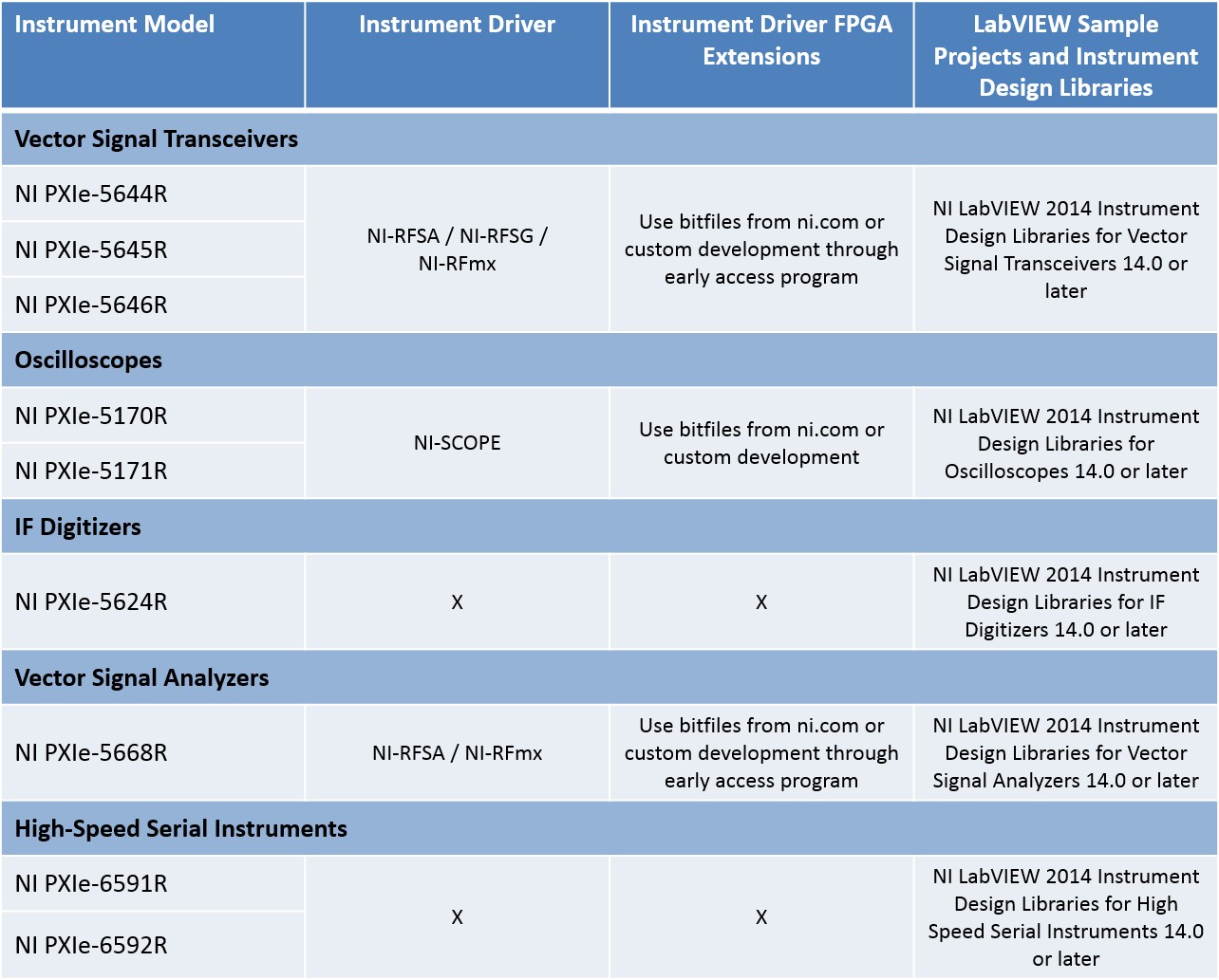
Not all software-designed instruments currently support all programming options. Software-designed instrument hardware may release before all options are available, and additional support may be added in the future or made available in the interim through an early access program. Furthermore, not all instruments necessarily fit the traditional instrument driver paradigm. For instance, NI high-speed serial instruments do not have an existing instrument driver that suits their intended use.
Figure 15. Currently Supported Programming Options for NI Software-Designed Instruments
Next Steps
- For more information on instrument driver FPGA extensions, read An Introduction to Instrument Driver FPGA Extensions for NI Software-Designed Instruments.
