Measuring Torque with Bridge-Based Sensors
This document provides information to help you understand fundamentals of torque measurements and how different sensor specifications impact torque sensor performance in your application. After you decide on your sensors, you can consider the required hardware and software to properly condition, acquire, and visualize torque measurements. You can also consider any extra signal conditioning you may need.
What is Torque?
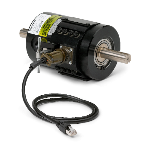
Force is the measure of interaction between bodies: for every action there is an equal and opposite reaction. Force is also described as a push or pull on an object. It is a vector quantity with both magnitude and direction.
Torque is the tendency of a force to rotate an object about an axis. Similar to force being described as push or pull, torque can be described as a twist to an object. The recognized SI unit of measure for torque is Newton-meters (Nm). Using a simple definition, torque is equivalent to force times distance, where a clockwise torque or twist is usually positive and a counterclockwise torque is usually negative. Torque sensors are composed of strain gages that are affixed to a torsion bar. As the bar turns, the gages respond to the bar’s sheer stress, which is proportional to the torque.
Measuring Torque
There are two common ways to measure torque: reaction torque sensors and rotary torque sensors—the major difference being whether it can rotate with the device under test.
Reaction Torque Sensors
Reaction torque is the turning force, or moment, imposed on the stationary portion of a device by the rotating portion as power is delivered or absorbed. If the load source is held rigid while the drive source is trying to rotate, the torque is sensed. Reaction torque sensors are restrained so they cannot rotate 360 degrees without the cable wrapping up because the housing or cover is fixed to the sensor element. These sensors are commonly used to measure torque of a back-and-forth agitating type motion. Because these sensors do not use bearings, slip rings, or any other rotating elements, their installation and use can be very cost-effective.
Rotary Torque Sensors
Rotating torque sensors are similar in design and application to reaction torque sensors except that the torque sensor is installed in line with the device under test. Since the shaft of a torque sensor is rotating 360 degrees, these sensors must have a way to transfer the signals from the rotational element to a stationary surface.
You can accomplish this by using one of three common mounting methods: slip rings, rotary transformers, or telemetry.
Slip Ring Method:
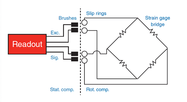
For the slip ring method, the strain gage bridge is connected to four silver slip rings mounted on the rotating shaft. Silver graphite brushes rub on these slip rings and provide an electrical path for the incoming bridge excitation and the outgoing signal. You can use either AC or DC to excite the strain gage bridge.
Rotary Transformer Method:
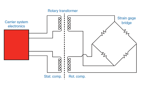
For the transformer method, the rotating transformers differ from conventional transformers only in that either the primary or secondary winding is rotating. One transformer is used to transmit the AC excitation voltage to the strain gage bridge and a second transformer is used to transfer the signal output to the nonrotating part of the transducer. Thus, two transformers replace four slip rings, and no direct contact is required between the rotating and stationary elements of the transducer.
Digital Telemetry Method:
The digital telemetry method has no contact points. The system consists of a receiver-transmitter module, coupling module, and signal processing module. The transmitter module is integrated in the torque sensor. It amplifies, digitizes, and modulates the sensor signal onto a radio frequency carrier wave that is picked up by the caliper coupling module (receiver). The digital measurement data is then recovered by the signal processing module.
Choosing the Right Torque Sensor
Torque sensor selections primarily depend on your capacity needs and physical or environmental requirements.
Capacity—To select the correct capacity, determine the minimum and maximum torque you expect. Extraneous torque and moments can increase the combined stress, which accelerates fatigue and affects sensor accuracy and performance. Any load other than torque, such as axial, radial, or bending, is considered extraneous and should be determined beforehand. If you cannot arrange your installation to minimize the effects of these loads, consult the sensor documentation to verify that the extraneous loads are within the sensor’s ratings.
Physical and environmental requirements—Evaluate any physical constraints (length, diameter, and so on) and the way the torque sensor can be mounted in your system. Consider what type of environment the sensor will be operating in to ensure proper performance across wide temperature ranges, humidity, or contaminants (oil, dirt, dust).
Revolutions per minute (rpm)—For rotary torque sensors, you need to understand how long the torque sensor will be rotating and at what speed to determine the RPM.
Signal Conditioning for Torque Sensors
Torque sensors can be either conditioned or nonconditioned. You can connect conditioned sensors directly to a DAQ device because they contain the required components for filtering, signal amplification, and excitation leads along with the regular circuitry for measurement. If you are working with nonconditioned sensors, you must consider several signal conditioning elements to create an effective bridge-based torque measurement system. You many need one or more of the following items:
- Excitation to power the Wheatstone bridge circuitry—learn more in the measuring strain resource
- Remote sensing to compensate for errors in excitation voltage from long lead wires
- Amplification to increase measurement resolution and improve signal-to-noise ratio
- Filtering to remove external, high-frequency noise
- Offset nulling to balance the bridge to produce 0 V when no strain is applied
- Shunt calibration to verify the output of the bridge to a known, expected value
To learn how to compensate for these errors and review other hardware considerations for bridge-based torque measurements, download the Engineer's Guide to Accurate Sensor Measurements.
Connecting Torque Sensors to NI Hardware
After you know your sensor or test needs, deciding on the hardware to collect that data is the next important step. The acquisition hardware’s quality determines the quality of the data you collect.
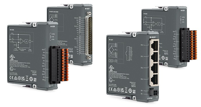
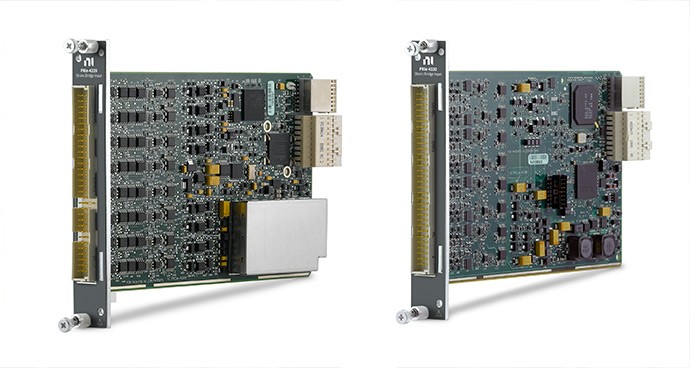
NI offers a range of force and bridge measurement hardware that is designed to acquire torque data and is compatible with a variety of torque bridge-based sensors.
Simple Hardware Setup
Pair Your Torque Sensor with Recommended Hardware
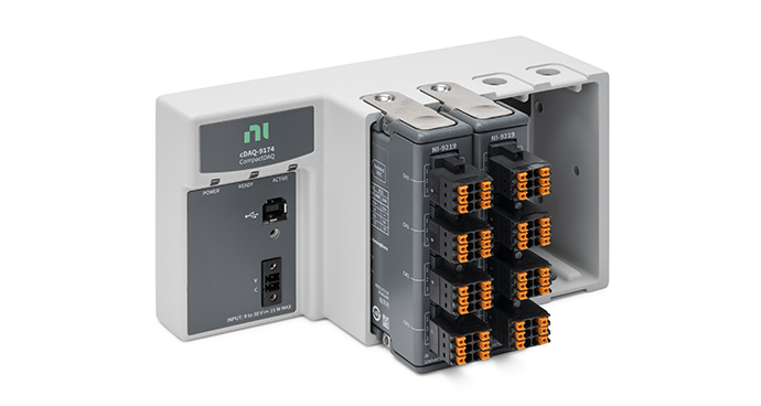
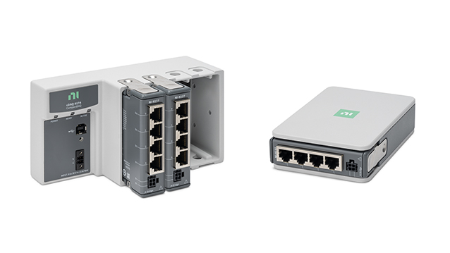
The CompactDAQ Strain and Load Bundle simplifies connecting your torque sensor with a bundle of strain/bridge input module(s) and a CompactDAQ chassis.
Other Products for Measuring Torque
The following products can interface with torque sensors. These products can also acquire pressure, force, and torque measurements. Learn more about measuring pressure with bridge-based or other pressure sensors, strain with strain gages, or load with bridge-based load cells to choose the right sensors and use with NI products.
References
- http://sensing.honeywell.com/white-paper-effectivelyusingpressureloadandtorquesensorswithtodaysdataacqusitionsystems-008883-2-en.pdf
- http://www.pcb.com/linked_documents/force-torque/catalog/sections/ftq200g_0107_6.pdf
- http://www.futek.com/load_cell_selection.aspx
- http://www.himmelstein.com/images/B705.pdf
