Measuring Sound with Microphones
This document will help you understand the fundamentals of sound pressure, how microphones work, and how different sensor specifications impact microphone performance in your application. After you decide on sensors, you can consider the required hardware and software to properly condition, acquire, and visualize microphone measurements. You can also consider any extra signal conditioning you may need.
What Is Sound Pressure
Pressure variations, whether in the air, the water, or another medium the human ear can detect, are considered sounds. The human eardrum transfers pressure oscillations, or sound, into electrical signals that our brains interpret as music, speech, noise, and so on. Microphones are designed to do the same thing. You can then record and analyze these signals to gather information about the nature of the path the sound took from the source to the microphone. For example, in noise, vibration, and harshness test, engineers are usually interested in reducing undesirable sounds, such as the noise passengers in a car experience while driving. These sounds could include sounds that are above or below the frequencies the human ear can detect or amplitudes at specific resonant frequencies. These measurements are important to designers who need to reduce noise to meet emissions standards or to characterize a device for performance and longevity.
Sound pressure is the most common measurement performed because humans are exposed to sound and can detect sound pressure. Measured in pascals (Pa), the sound pressure level represents how a receiver perceives sound. You can also determine the sound power of a source. Measured in watts (W), the sound power level represents the total acoustic energy that is radiated in all directions. It is independent of the environment including the room, receivers, or distance from the source. Power is a property of the source, whereas sound pressure depends on the environment, reflecting surfaces, the distance of the receiver, ambient sounds, and so on.
Measuring Sound with Microphones
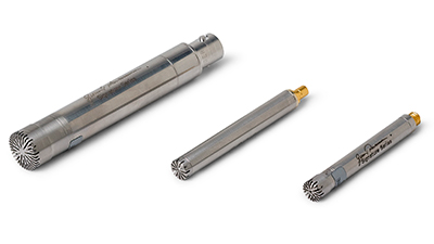
You can choose from a few different designs for microphones, but the most common instrumentation microphones are externally polarized condenser microphones, prepolarized electret condenser microphones, and piezoelectric microphones.
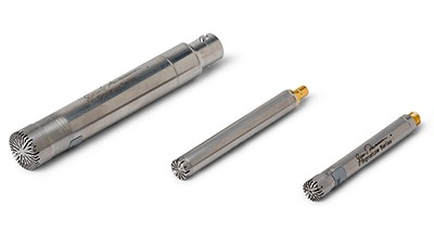
Figure 1. A microphone is a transducer that converts acoustical waves into electrical signals.
Condenser Microphones
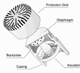
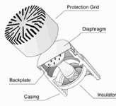
A condenser microphone operates on a capacitive design. It incorporates a stretched metal diaphragm that forms one plate of a capacitor. A metal disk placed close to the diaphragm acts as a backplate. When a sound field excites the diaphragm, the capacitance between the two plates varies according to the variation in the sound pressure. A stable DC voltage is applied to the plates through a high resistance to keep electrical charges on the plate. The change in the capacitance generates an AC output proportional to the sound pressure. The charge of this capacitor is generated either by an external polarizing voltage or by the properties of the material itself, as in the case of prepolarized microphones. Externally polarized microphones need 200 V from an external power supply. Prepolarized microphones are powered by IEPE preamplifiers that require a constant current source.
Figure 2. The most common instrumentation microphone, a condenser microphone, operates on a capacitive design.
Piezoelectric Microphones
Piezoelectric microphones use a crystal structure to generate the backplate voltage. Many piezoelectric microphones use the same signal conditioning as accelerometers and may use IEPE signal conditioning to provide the polarization voltage. Although these sensor-type microphones have low sensitivity levels, they are durable and able to measure high amplitude pressure ranges. Conversely, the floor noise level on this type of microphone is generally high. This design is suitable for shock and blast pressure measurement applications.
Choosing the Right Microphone
When choosing the optimal microphone, consider the type of response field, dynamic response, frequency response, polarization type, sensitivity required, and temperature range. There are also a variety of specialty type microphones for specific applications. In order to select and specify a microphone, the first criteria that needs to be looked at is the application and what the sound and environment represent.
For more details about the components and design of microphones, refer to the Microphone Handbook.
Consider the Microphone Response Field
You must choose the microphone that is best for the type of field in which you will operate it. The three types of measurement microphone are free field, pressure field, and random incidence. These microphones operate similarly at lower frequencies but differently at higher frequencies.
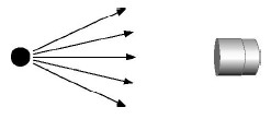
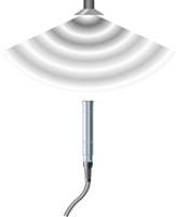
The most common microphone is a free-field microphone. It measures the sound pressure from a single source directly at the microphone diaphragm. It measures sound pressure as it existed before the microphone was introduced into the sound field. These microphones work best in open areas free of hard or reflective surfaces. Anechoic chambers or larger open areas are ideal for free-field microphones.
Figure 3. Free-Field Microphone
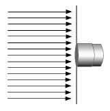
A pressure-field microphone is designed to measure the sound pressure in front of the diaphragm. It has the same magnitude and phase at any position in the field. It is usually found in an enclosure, or cavity, which is small when compared with wavelength. Pressure-field microphone application examples include testing the pressure exerted on walls, on airplane wings, or inside structures such as tubes, housings, or cavities.
Figure 4. Pressure-Field Microphone
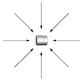
In many situations, the sound is not traveling from a single source. Random-incidence or diffuse-field microphones respond uniformly to sounds arriving simultaneously from all angles. You use this type of microphone when taking sound measurements in a church or an area with hard, reflective walls. However, for most microphones, the pressure and random-incidence responses are similar, so pressure-field microphones are often used for random-incidence measurements.
Figure 5.Random-Incidence Microphone
Select the Right Dynamic Range
The main criterion for describing sound is based on the amplitude of the sound pressure fluctuations. The lowest amplitude that a healthy human ear can detect is 20 millionths of a pascal (20 μPa). Since the pressure numbers represented by pascals are generally low and not easily managed, another more commonly used scale, the decibel (dB) scale, was developed. This logarithmic scale more closely matches the response reactions of the human ear to the pressure fluctuations. Here are some examples of typical sound pressure levels to use as a reference:
Level References
| 0 dB = 0.00002 Pa | Threshold of Hearing |
| 60 dB = 0.02 Pa | Business Office |
| 80 dB = .2 Pa | Shop Noise |
| 94 dB = 1 Pa | Large Truck |
| 100 dB = 2 Pa | Jackhammer |
| 120 dB = 20 Pa | Airplane Take-Off |
| 140 dB = 200 Pa | Threshold of Pain |
Manufacturers specify the maximum decibel level based on the design and physical characteristics of the microphone. The specified maximum dB level refers to the point where the diaphragm approaches the backplate, or where total harmonic distortion (THD) reaches a specified amount, typically 3 percent THD. The maximum decibel level that a microphone generates in a certain application depends on the voltage supplied and that particular microphone’s sensitivity. Before you can calculate the maximum output for a microphone using a specific preamplifier and its corresponding peak voltage, you first need to calculate the pressure in pascals that the microphone can accept. You can calculate the amount of pressure using the following formula:
Where P = pascals (Pa) and voltage is the preamplifier output peak voltage.
After determining the maximum pressure level that the microphone can sense at its peak voltage, you can convert this amount to decibels (dB) using the following logarithmic scale:
Where P = pressure in pascals
Po = reference pascals (constant = 0.00002 Pa)
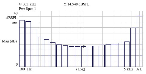
This formula provides the maximum rating that a microphone, when combined with a specific preamplifier, is capable of measuring. For the low-end noise level, or minimum amount of pressure required, you need to review the cartridge thermal noise (CTN) rating of the microphone. The CTN specification provides the lowest measurable sound pressure level that can be detected above the electrical noise inherent within the microphone. Figure 6 shows the typical representation of the noise level at different frequencies for a microphone when used in conjunction with a preamplifier.
Figure 6. The inherent noise level is greatest at upper and lower capabilities of the microphone.
When selecting a microphone, you must confirm that the pressure levels you are testing fall between the microphone’s CTN and the maximum-rated decibel level of the microphone. In general, the smaller the microphone diameter, the greater the high-end decibel level is. The larger diameter microphones typically have lower CTN, so they are recommended for low-range decibel measurements.
Review Specifications to Evaluate Frequency Response
After you consider the type of microphone field response and dynamic range you need, review the microphone’s specification sheet to find the usable frequency range (Hz). Smaller diameter microphones usually have a higher upper frequency level capability. Conversely, larger diameter microphones are more sensitive and better suited to detect lower frequencies.
Manufacturers place a typical tolerance of ±2 dB on the frequency specifications. When comparing microphones, ensure you check the frequency range and the tolerance associated with that specific frequency range. If an application is not critical, you can improve the usable frequency range for that microphone if you are willing to increase your allowable decibel tolerance. You can check with the manufacturer or look at the calibration sheet for a particular microphone to determine the actual usable frequency range for specific decibel tolerances.
Decide on Polarization Type
Traditional externally polarized and modern prepolarized microphones work well for most applications, but they do have some differences. Externally polarized microphones are recommended for high temperatures (120 °C to 150 °C) because the sensitivity level is more consistent in this range. Prepolarized microphones tend to be more consistent in humid conditions. Sudden changes in temperature that result in condensation on internal components may short out externally polarized microphones.
Because externally polarized microphones require a separate 200 V power source, you are limited to 7-conductor cabling with LEMO connectors in this setup. The newer, prepolarized microphones have become more popular because they are powered by an easy-to-use, 2–20 mA constant current supply. With this design, you can use standard coaxial cables with BNC or 10-32 coaxial connectors for both current supply and signal to the readout device.
Know Your Temperature Range
Microphone sensitivity decreases as the temperature approaches the maximum specifications of the microphone. You must be aware of not only the operating temperature but also the storage temperature of the microphone. Operating and/or storing a microphone in extreme conditions can adversely affect it and increase its calibration needs. In many cases, the required preamplifier can be the limiting factor for operating temperature range. Although most microphones can operate to 120 °C without any loss of sensitivity, the preamplifiers required for these microphones typically operate in the 60 °C to 80 °C range.
Use a Specialty Microphone for Particular Applications
When temperature becomes a concern, a probe microphone offers an alternative solution. The probe microphone was designed for sound pressure measurements in harsh environments. It combines a microphone with a probe extension tube. This enables the user to get very close to sound sources. The probe tip will send the acoustic signal to the microphone inside the probe housing. By placing some of the critical components in the separate housing, this microphone type can be used in extremely high temperature applications, or where access to the sound source is too small for a typical condenser microphone.
Applications that require a microphone to be fully submersible provide their own challenges. Hydrophones were designed to detect underwater sound pressure signals. Industrial and scientific underwater testing, monitoring and measurements are accomplished with this corrosion resistant design. Different models are available for different sensitivities, frequencies decibel levels and operating depths.
Sound Level Meters are designed by manufacturers to provide a fast and convenient way to obtain a sound pressure level reading. This design contains all the components necessary to take a sound pressure reading. This small handheld unit includes the microphone, preamplifier, power source, software and display. This is an excellent choice for taking a dB measurement in an industrial setting, for community noise assessment, noise exposure measurements, artillery fire measurements, and many other applications. The Sound Level Meter can be provided with a number of options, including A Weighting, real time analyzers, and software options.
When measurements involving the magnitude and direction of the sound needs to be captured, an intensity probe is an excellent choice. By taking two phase matched microphones and placing a spacer between them, a user can not only tell the pressure level, but also the speed and direction of the propagating sound waves. Different sized spacers are available for measuring the particle velocity at different frequencies. The higher frequencies typically require a smaller spacer. Larger spacers are suitable for lower frequencies and for situations where reverberation is present.
For Near Field Acoustic Holography (NAH) applications where three dimensional field values are to be studied, an Array microphone set-up is recommended. By taking a number of array microphones and spacing them out in a predetermined pattern, and combining them with the appropriate software, spatial transformation of a complex sound pressure field is projected to effectively map the acoustic energy flow. Array microphones are an excellent choice for large channel count acoustic testing. Transducer Electronic Data Sheet (TEDS) are a recommended option for arrays, since they enable the user to quickly and easily identify a particular microphone. These TEDS chips and software enable the user to store information on the microphones model, serial number, calibration date, along with the specifications of the microphones sensitivity, capacitance, impedance, etc… that can be downloaded and help ensure accurate test results.
Outdoor microphones have been developed to be able to withstand the rigorous environmental exposure that these microphones will be subjected to. Airport noise, or highway traffic noise has become increasing popular spots for test and measurements, to provide safety for humans. The Environmental microphones and Outdoor microphones provide different levels of protection for the internal components, while maintaining their high-accuracy specifications.
Looking for a sensor?
NI offers a few G.R.A.S. microphones. Learn more with G.R.A.S. Selection Guide for Microphones and Preamplifiers.
Signal Conditioning for Microphones
When preparing a microphone to be measured properly by a DAQ device, you need to consider the following to ensure you meet all your signal conditioning requirements:
- Amplification to increase measurement resolution and improve signal-to-noise ratio
- Current excitation to power the preamplifiers in IEPE sensors
- AC coupling to remove DC offset to increase resolution and take advantage of the full range of the input device
- Filtering to remove external, high-frequency noise
- Proper grounding to eliminate noise from the current flow between different ground potentials
- Dynamic range to measure the full amplitude range of the microphone
To better familiarize yourself with the measurement hardware and software processing necessary for microphone measurements, download the Engineer's Guide to Accurate Sensor Measurements.
Connecting Microphones to NI Hardware
After you know your sensor or test needs, deciding on the hardware to collect that data is the next important step. The acquisition hardware’s quality determines the quality of the data you collect.
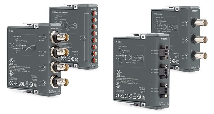
NI offers a variety of Sound and Vibration Hardware that is designed to acquire sound data and is compatible with a variety of IEPE sensors.
To help verify compatibility between an NI Sound and Vibration device and an IEPE sensor, microphone, and so on, use the Excitation & Compliance Voltage for IEPE Sensors guide. If a preamplifier is used, NI sound and vibration hardware still works, but the signal characteristics may change. Verify the output of the preamplifier is within the sound and vibration hardware input range. Likewise, for non-IEPE sensors, ensure the sensor output is compliant with device input capabilities.
Simple Hardware Setup
Pair Your Microphone with Recommended NI Hardware
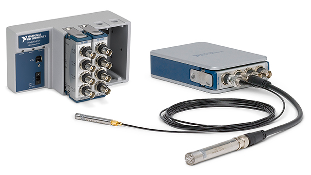
The CompactDAQ Sound and Vibration Bundle simplifies connecting your microphone or sound pressure sensor with a bundle of sound and vibration module(s) and a CompactDAQ chassis.
Other Products for Measuring Sound
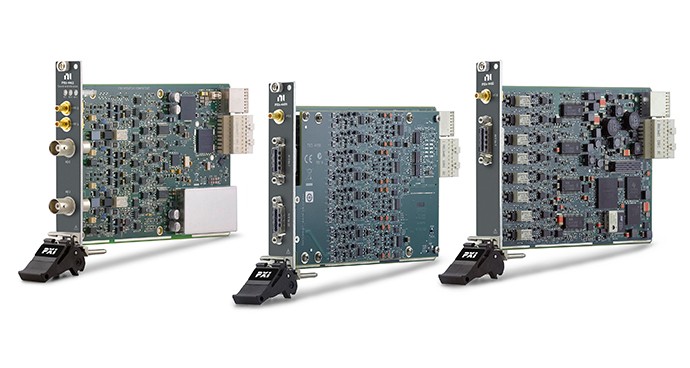
The following products interface with microphones to acquire acoustic signals. Use these products for audio test; machine condition monitoring; and noise, vibration, and harshness (NVH) applications. These products work for both sound and vibration measurements. Learn more about measuring vibration with accelerometers to pair with NI products.
References
- "Microphone Handbook." pcb.com, 2013. https://www.pcb.com/microphonehandbookfiles/microphone_handbook_lowres.pdf
