Image Acquisition
Contents
Cameras
You can choose between two main types of cameras – analog and digital. Digital cameras can be further classified into parallel digital, Camera Link, and IEEE 1394. The following sections contain information about these cameras and their advantages and disadvantages, which can help you choose the right camera for your application.
Analog Cameras
Analog cameras are cameras that generate a video signal in analog format. The analog signal is digitized by an image acquisition device. The video signal is based on the television standard, making analog the most common standard for representing video signals.
You may have heard the term charge-coupled device (CCD), and wondered how it relates to the analog video signal. A CCD is an array of hundreds of thousands of interconnected semiconductors. Each pixel is a solid-state, photosensitive element that generates and stores an electric charge when it is illuminated. The pixel is the building block for the CCD imager, a rectangular array of pixels on which an image of the scene is focused. In most configurations, the sensor includes the circuitry that stores and transfers its charge to a shift register, which converts the spatial array of charges in the CCD imager into a time-varying video signal. Timing information for the vertical and horizontal positions and the sensor value combine to form the video signal.
For standard analog cameras, the lines of the CCD are interlaced to increase the perceived image update rate. This means that the odd-numbered rows (the odd field) are scanned first. Then the even-numbered fields (the even field) are scanned. The two fields make up one frame. Electronic Industries Association (EIA) RS-170 and NTSC cameras update at 30 frames/s with a resolution of 640 columns x 480 rows. CCIR and PAL cameras update at 25 frames/s with a resolution of 768 columns x 576 rows.
Analog cameras are low in cost and easy to interface with a standard analog acquisition device. Therefore, they can solve numerous applications at an attractive price.
Digital Cameras
Digital cameras have several advantages over analog cameras. Analog video is more susceptible to noise during transmission than digital video. By digitizing at the camera level rather than at the image acquisition device, the signal-to-noise ratio is typically higher, resulting in better accuracy. Because digital cameras are not required to conform to television standards, they can offer larger image sizes and faster frame rates, as well as higher pixel resolutions. Digital cameras come with 10 to 16-bit gray levels of resolution as a standard for machine vision, astronomy, microscopy, and thermal imaging applications. Digital cameras use the same CCD type devices for acquiring images as analog, they simply digitize the video before sending it to the frame grabber.
Parallel Digital Cameras
Until recently, parallel digital cameras were the only type of digital cameras available. They offer all of the benefits mentioned above. However, parallel digital cameras have no clear physical or protocol standards, and interfacing to digital acquisition devices can be difficult. Parallel digital cameras often require custom cables to connect with image acquisition devices. You also must be certain that your camera is compatible with your image acquisition device.
Fortunately, a large base of parallel cameras exists on the market for almost any imaging application. National Instruments provides cables and camera configuration files to make connecting to parallel digital cameras easy. To determine whether one of the NI acquisition devices is compatible wiith your camera, visit Camera Advisor on ni.com.
Camera Link
Camera Link is an interface specification for cables that connect digital cameras to image acquisition devices. It preserves the benefits of digital cameras – such as flexibility for many types of sensors – yet it has only a small connector and one or two identical cables, which work with all Camera Link image acquisition devices. Camera Link greatly simplifies cabling, which can be a complex task when working with standard digital cameras. To determine whether one of the NI acquisition devices is compatible with your camera, visit Camera Advisor on ni.com.
IEEE 1394
IEEE 1394 is a serial bus standard used by many PC peripherals, including digital cameras. IEEE 1394 cameras use a simple, flexible, 4 or 6-wire power cable; and in some cases, the bus can supply power to the camera. However, because IEEE 1394 is a shared bus, there is a bandwidth limitation of approximately 40 MB/s when no other device is connected to the bus. IEEE 1394 cameras also require processor control to move the image data, which limits available processor bandwidth for image processing.
IEEE 1394 is a standard that also includes functions for enumerating and setting up the camera capabilities. You can acquire images from any industrial IEEE 1394 camera and OHCI-compliant IEEE 1394 adapter using NI-IMAQ for IEEE 1394 Cameras driver software, which you can purchase at ni.com.
Important Camera Technologies
Progressive Scan
In standard analog cameras, the CCD is exposed and read in two fields – the odd field and the even field. When imaging an object in motion, the interlacing of the odd and even fields of the CCD sensor causes a double exposure of the image, as shown in Figure 1.
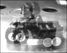
Figure 1: Images of a Moving Object Taken with a Standard Analog Camera
In progressive-scan cameras, the CCD sensor array is exposed at the same time rather than in two steps. This behavior makes progressive-scan cameras especially useful in applications where the object under inspection moves. However, you need to set the appropriate exposure time in order to acquire images without motion-induced blur. Figures 2a, 2b, and 2c are images of a moving toy motorcycle taken with a progressive scan camera using exposure times of 33, 10, and 1 ms, respectively.
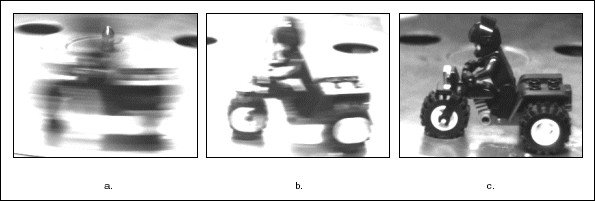
Figure 2: Images of a Moving Toy Motorcycle Taken with a Progressive-Scan Camera Using Exposure Times of 33 ms, 10 ms, and 1 ms, Respectively
National Instruments PC-1407, PXI-1407, and PCI-1409 image acquisition devices work with progressive-scan and standard analog cameras.
Line Scan
Unlike an area-scan camera, which acquires a 2D image, a line-scan camera acquires an image that is only one pixel wide. Figure 3 illustrates the concept of a line scan camera acquiring images of a nut, one "line" (or pixel) at a time.
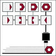
Figure 3: Concept of a Line-Scan Acquisition
Line-scan cameras are useful in web inspection applications during which the object under inspection moves along a conveyor or stage in a production system. Line-scan cameras are also useful in high-resolution applications because you can acquire lines at a fast rate as the part moves. You can use the PCI-1424, PCI-1428, PCI-1422, and PXI-1422 devices with digital line-scan cameras, as well as the PCI-1409 with analog line-scan cameras. The width of line-scan cameras is fixed by the number of CCDs in the camera, but with the NI-IMAQ driver, you can make the image height arbitrary (must fit in onboard memory – 32 to 80 MB), depending on the size of the object to inspect. This is called variable height acquisition (VHA).
Infrared
Infrared (thermal) cameras measure the infrated, or thermal, energy emitted from a scene. Infrared cameras can help solve some scientific and industrial applications that sensors using the visible spectrum of light cannot solve. You can see many defects easier in the infrared spectrum. You can also measure the contents of containers if the contents are a different temperature than the container. For example, you can use an infrared camera to see the oil level in a compressor when the oil temperature differs from the casing temperature.
National Instruments image acquisition devices make it simple to acquire and process thermal images. You can acquire images from infrared cameras, including some high-resolution digital cameras. Then you can analyze the thermal images with IMAQ Vision image analysis functions. Figure 4 shows a thermal image of a printed circuit board (PCB). The yellow and red areas of the image represent hotspots on the board.
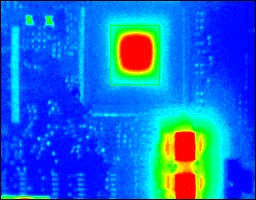
Figure 4: Using Thermal Imaging to Detect Hotspots on a PCB
Choosing the Right Camera
The following table compares different types of cameras.
Table 1
| Analog Cameras | Parallel Digital Cameras | Camera Link Cameras | IEEE 1394 Cameras | |
| Data Rate | Slow | Fast | Fast | Slow |
| Spatial Resolution | Low | High | High | Medium |
| Functionality | Simple and easy | Advanced | Advanced | Simple and easy |
| Pixel Depth | 8-bit to 10-bit | Up to 16-bit | Up to 16-bit | Typically 8-bit |
| Cabling | Simple BNC cabling | Thicker, custom cabling | Simple, standard cabling | Simple, standard cabling |
Image Acquisition Hardware
You should consider the following hardware features for your machine vision or scientific imaging applications:
- Onboard memory
- Fast data transfer to PC memory
- Advanced triggering
- Integration with data acquisition and motion control hardware
- Preprocessing functions.
National Instruments high-speed image acquisition (IMAQ) devices provide up to 80 MB of onboard memory. With onboard memory, you can acquire at extremely high rates while sustaining high-speed throughput and greater overall system performance.
NI uses state-of-the-art digital technology to maximize throughput over the PCI bus. Using this technology, you can acquire images from high-speed digital cameras with low latency and no loss of data.
National Instruments IMAQ devices connect to parallel digital, analog, and Camera Link cameras. These devices include advanced triggering and digital I/O features that you can use to trigger an acquisition based on a digital signal from photocells or proximity switches. You can also use digital I/O signals to control strobe lights or relay devices.
Most IMAQ devices work with motion control and data acquisition hardware using the RTSI bus. On National Instruments PCI boards, the RTSI bus connector sits on the top of the board. You can use a ribbon cable to connect RTSI connectors on adjacent boards and send triggering and timing information from one board to another. On National Instruments PXI modules, the PXI trigger bus on the PXI backplane replaces the RTSI bus.
IMAQ devices, which offer preprocessing to can improve the performance of your application, can perform such tasks as pixel and line scaling (decimation) and region-of-interest acquisition. NI offers a wide variety of machine vision hardware, including frame grabbers, cameras, and lenses.
Learn how to choose the right camera bus for you
NI-IMAQ Driver Software
Whether you are using LabVIEW, Measurement Studio, Visual Basic, or Microsoft Visual C++, the NI-IMAQ driver software gives you control of National Instruments image acquisition devices. NI-IMAQ is a complete, robust API for image acquisition. It performs all the computer and device-specific tasks for straightforward image acquisition without register-level programming. NI-IMAQ is included with the purchase of any IMAQ device, free of charge.
Figure 5 shows how easy it is to use NI-IMAQ with the IMAQ Vision for LabVIEW image processing library. With only three icons in LabVIEW, you can snap and display an image. You can easily build more complex configurations using this LabVIEW diagram as a foundation.
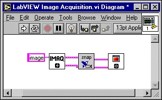
Figure 5: A Simple LabVIEW Diagram that Acquires and Displays an Image
The following is the IMAQ Vision for LabWindows/CVI code that performs the same snap as the diagram in Figure 5.
// This sample demonstrates how to acquire a picture using a high level snap operation
#include "stdafx.h"
#include <windows.h>
#include "snap.h"
#define _NIWIN
#include "niimaq.h"
int main(int argc, char* argv[])
{
// Window Handle of the display window
static HWND ImaqSmplHwnd;
// Imaq globals
static SESSION_ID Sid = 0;
static INTERFACE_ID Iid = 0;
static Int8* ImaqBuffer=NULL;
// Create a window to display the image
ImaqSmplHwnd = CreateIMAQWindow();
// Open an interface and a session
imgInterfaceOpen("img0", &Iid);
imgSessionOpen(Iid, &Sid);
// Snap a picture
ImaqBuffer = NULL;
imgSnap(Sid, (void **)&ImaqBuffer);
// Display using NI-IMAQ
imgPlot((GUIHNDL)ImaqSmplHwnd, (void *)ImaqBuffer, 0, 0, 640, 480, 0, 0, IMGPLOT_MONO_8);
// Close the interface and the session
imgClose(Sid, TRUE);
imgClose(Iid, TRUE);
return 0;
}
Lastly, the following is the IMAQ Vision for Visual Basic code that performs the same snap operation as the above code and the diagram in Figure 5.
Private Sub Snap_Click()
'Get the interface name and load the parameters set in
'Measurement & Automation Explorer (MAX)
CWIMAQ1.Interface = IntfName.Text
CWIMAQ1.LoadInterfaceDefaults
'Acquire asynchronously one buffer
CWIMAQ1.AcquireImage
'Display the most recently acquired picture in a Picture Box
'Note that it could be done more simply with the CWIMAQViewer object
'whose demo version is given, see the "Snap in CWIMAQViewer" sample
CWIMAQ1.WindowPlot Display.hWnd
End Sub
Private Sub Quit_Click()
End
End Sub
Once you write code to use with a particular image acquisition device or camera, you do not need to alter the code if you change to another IMAQ device. NI-IMAQ works identically across National Instruments entire product line of image acquisition devices and across a broad range of cameras.
NI-IMAQ is compatible with NI-DAQmx and all other National Instruments driver software, making it easy to integrate imaging into any National Instruments solution.
NI-IMAQ is an extensive library of high-level and low-level functions that you can call from your application development environment. High-level functions include single-shot and continuous-mode image acquisition. Low-level functions include imaging sequence setup. Other functions include routines for video configuration, memory buffer allocation, trigger control, and device configuration. NI-IMAQ provides all the functionality you need to acquire images and communicate with your camera. For image analysis and processing functionality, see the Analyze and Process Images section.
NI-IMAQ internally resolves many of the complex issues between the computer and IMAQ hardware, such as programming interrupts and DMA controllers. NI-IMAQ provides the interface path between the hardware product and LabVIEW, Measurement Studio, and other programming environments.
National Instruments Configuration Software
You can easily configure your image acquisition system with Measurement & Automation Explorer (MAX), which comes with NI-IMAQ. MAX is an interactive tool for configuring National Instruments hardware devices. You can use MAX to select the type of camera (RS-170, CCIR, NTSC, PAL, and nonstandard) you are using. You can also set parameters for the region of interest, black and white levels, antichrominance filter, asynchronous acquisition, gain, and exposure time. Additionally, you can use MAX to set up acquisitions from noninterlaced progressive scan cameras. You can also create your own camera configurations for nonstandard video by setting the VSYNC, HSYNC, and other timing information.
Scalability
NI-IMAQ driver software is designed to scale between many types of acquisition methods, as shown in Figure 6. This design consideration means that you can start using a low-cost, RS-170 camera and image acquisition device and upgrade later to a faster, higher-resolution camera and device with minimal software changes. To start using a new camera or device, all you need to do is configure the new hardware in MAX, the configuration utility for NI devices. Because NI-IMAQ uses one set of function calls that work for a wide variety of cameras, you do not need to rewrite your software.
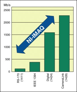
Figure 6: Using NI-IMAQ, You Can Interchange Cameras without Rewriting Your Application.
NI Vision Application Software
NI vision hardware is compatible with a variety of vision acquisition software, which makes it easy to configure cameras, customize image analysis, and generate inspection results. The Vision Development Module helps you program and configure vision algorithms and image processing in LabVIEW. Vision Builder for Automated Inspection (AI) is a menu-driven environment for configuring machine vision inspections and communicating with industrial hardware. Both products include Vision Acquisition Software, which enables you to acquire, display, and save images from a range of industry standard cameras interfaces including GigE Vision, USB3 Vision, and Camera Link. You can also use this software to conveniently control digital I/O on NI vision hardware. With a set of easy-to-use functions and example programs, you can quickly create applications using LabVIEW and C/C++. Compare your vision software options.