Rapidly Transitioning from Radar Simulation to Testbed
Overview
To deliver new capability and meet defense-acquisition timelines, radar researchers and systems engineers must move from concept to proof-of-concept quickly. Modeling and simulation using tools such as Python, C/C++, and MathWorks MATLAB® software are important to validate ideas and demonstrate early results before undertaking the potentially more costly process of testing with real-world signals in the lab or on the range. Migrating IP from simulation to a hardware testbed can be a sticking point if software tools are not designed to scale throughout the development cycle. And this is exacerbated if researchers and engineers are forced to build custom hardware, rather than utilizing off-the-shelf technologies for RF and digital I/O, signal processing, data movement, and storage. Let’s explore how to rapidly migrate IP from MathWorks tools for modeling and simulation to a radar prototyping testbed built upon NI COTS components.
The Concept
Everything begins with an idea.
And there are countless ideas to bring new capability to radar systems. Frequently, innovation comes in the form of novel waveforms, algorithms, and architectures, and new RF or digital components. Consider the impact of new algorithms on performance: If a radar system is drowned out by other signals or, worse, actively jammed, it will not effectively operate in a congested and contested spectrum. In this case, adaptive or cognitive techniques such as spectrum interference avoidance would increase frequency agility so that the radar could operate in less-congested spectrum. And what if the radar has difficulty determining targets against a cluttered background? Machine-learning, Gaussian-based approaches could be more effective than human operators at distinguishing targets from clutter.
On paper, these ideas look desirable. But ideas are cheap—actually implementing them can be time-consuming and costly. That’s why they require scrutiny before reaching the test range, let alone the field.
Modeling and Simulation
The first hurdle for a researcher looking to secure funding is to show that, conceptually, their idea is viable. It’s critical to explore the viability of a novel concept before spending time and money on testing it out with real-world hardware—and that’s why the modeling and simulation phase is so important.
Radar researchers and systems engineers often use tools such as MathWorks MATLAB software and MathWorks Simulink® software to interactively design waveforms and sensor arrays and to explore various complex trade-offs across the entire multifunction radar system workflow—from RF and antenna components to signal processing algorithms. Because you can design and debug complete radar models at the earliest stage of the project, you can preempt and eliminate costly redesigns and utilize automatically generated code within tactical systems.
For accelerated development, MathWorks offers libraries of algorithms—including matched filtering, adaptive beamforming, target detection, space-time adaptive processing, and environmental and clutter modeling—that you can customize for your specific application. Additionally, you can model ground-based, airborne, and ship-borne radar platform scenarios, as well as moving targets across many domains.
Consider a scenario in which you need to upgrade an existing radar system to increase the maximum unambiguous range, detect targets with rapidly varying radar cross sections (RCS), and avoid interference with newly deployed 5G networks. Let’s say that the existing radar system uses a pulsed waveform, with relatively low transmission power and high pulse repetition frequency (PRF). It is logical that increasing the pulse interval (therefore, reducing PRF) will help to meet the increased maximum range requirement. Also, one way to detect targets with fluctuating RCS would be to boost the signal-to-noise ratio (SNR) by transmitting at higher power. One of these changes likely is trivial (a software parameter update to reduce the waveform’s PRF) but increasing transmission power may require significant and expensive hardware updates. Experimenting within a simulated environment helps you evaluate this design space— either increasing confidence or sparking a pivot to explore alternatives—before implementing such costly changes. For example, an alternative approach might replace the basic pulsed waveform with a linear FM waveform to use lower peak transmit power. For interference avoidance, you’d need to develop new algorithms that sense the RF spectrum, so that the radar would behave in a cognitive or adaptive manner, shifting its operating frequency to find the least-congested spectral areas.
To validate whether this approach works for you, you can simulate the radar model, its surrounding environment, targets, and other EM signals within MATLAB. To see whether the radar will detect targets with fluctuating RCS, create targets with a variety of Swerling models. You then can use MATLAB and Simulink to explore whether the radar system modifications are sufficient, demonstrate their impact on the rest of the system, and deploy to software defined radio (SDR) hardware for real-world testing and implementation.
Moving from Simulation to Testbed
Having simulated the approach and demonstrated initial results in software, the next stage is to build out a full testbed to validate performance in lab conditions. Traditionally, moving algorithmic IP from simulation into hardware has been anything but simple. Code must be rewritten to:
- Run optimally across multiple computing architectures, such as FPGAs and GPUs
- Account for data movement between RF/digital instrumentation and heterogeneous processors
- Operate within real-time latency constraints
- Consider real-world imperfections and parametrics
If software tool flows are not designed to scale through the development process, it can be time-consuming to rewrite code to run on hardware.
With the right tools and some planning, you can accelerate the process of moving into hardware. Together, NI and MathWorks offer many routes from modeling and simulation to testbed.
At the most basic level, there are several ways to call MATLAB from LabVIEW:
- Interfaces for MATLAB—These are documents in which you define calls to a MATLAB file in your G dataflow application. When the application is executed, the MATLAB interface invokes MATLAB: Input data passes from the LabVIEW diagram to the MATLAB file for execution, then data is subsequently returned to the diagram.
- MATLAB Script Node—These nodes are added to a LabVIEW block diagram and invoke the MATLAB software script server to execute scripts written in MATLAB language syntax.
- Call Library Function Node—This method can be especially useful if you do not have access to a MATLAB license. Create a DLL from MATLAB, then call it in LabVIEW using the Call Library Function Node.
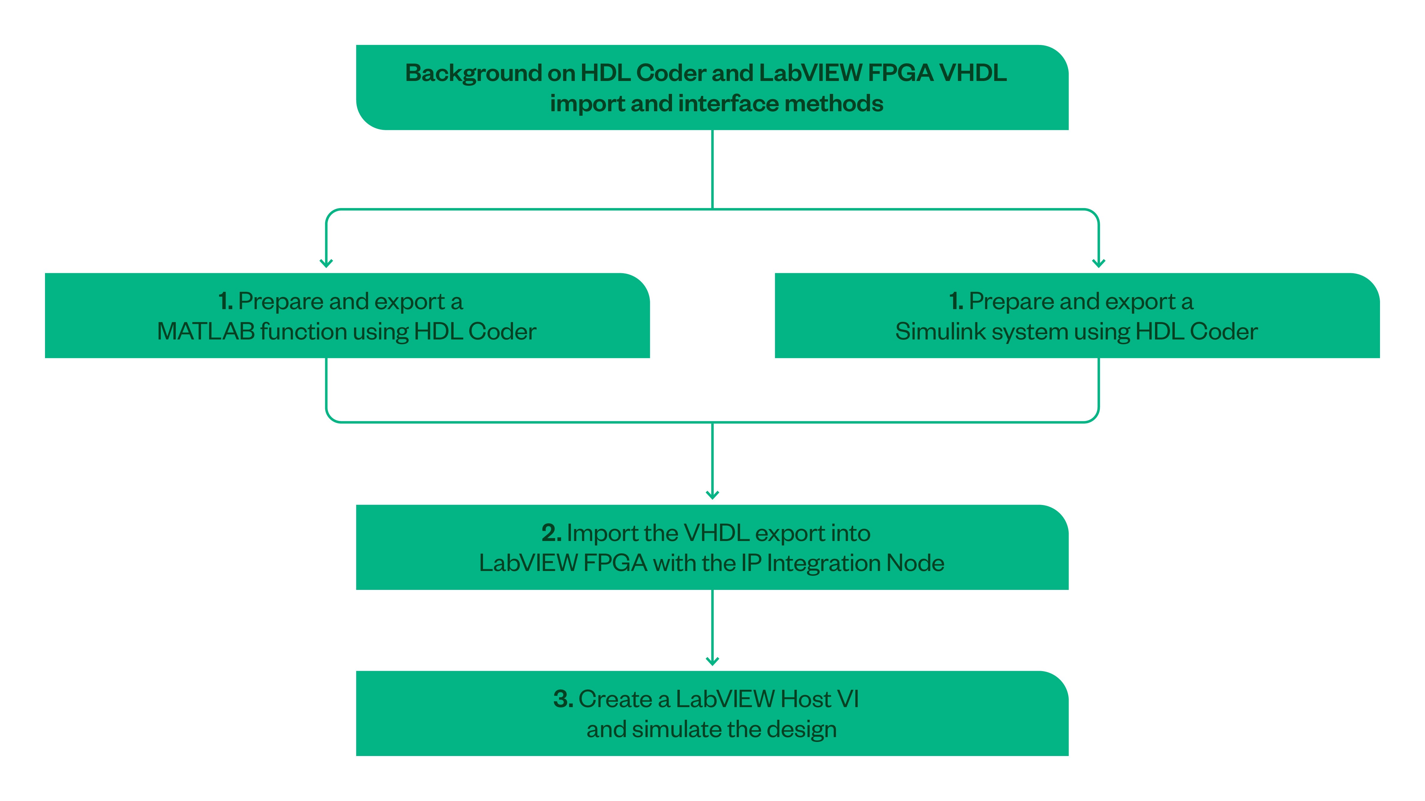
In addition to linking NI and MathWorks software, there are more direct methods of targeting NI and Ettus Research Universal Software Radio Peripheral (USRP) SDR devices from MATLAB or Simulink. HDL Coder is a tool that generates portable, synthesizable VHDL and Verilog code from MATLAB functions and Simulink models. You can integrate the generated HDL code into LabVIEW FPGA designs to rapidly introduce into hardware testbeds with real-world inputs and outputs. With correct planning and execution, this is a more efficient way to reuse algorithmic IP from software simulations. You then can utilize IP migrated into LabVIEW FPGA within a testbed built upon NI COTS FPGA-based hardware such as FlexRIO, USRP devices, or Vector Signal Transceivers.
When developing code, you should follow the principles discussed in Importing HDL Coder™ Exports into LabVIEW FPGA Designs. This document covers how to import an example model or algorithm written in MATLAB or Simulink, generate VHDL using HDL Coder, import into LabVIEW FPGA, and test on NI FPGA hardware connected to real-world inputs and outputs.
Figure 1.Integrating IP from HDL Coder into LabVIEW
Building the Testbed
If initial simulation results are promising, your next task involves building out a full testbed within which to fully validate new techniques', performance—either in the lab or on the range. There are a few ways that you can do this. One method involves building a custom testbed from components or evaluation boards. While this benefits from being built to exact specifications, it presents flexibility, scalability, and development-speed challenges. Custom designs require a broader set of skills (or a larger team with hardware and infrastructure design expertise). Worse yet, when validating a new paradigm, rarely does everything go according to plan at first attempt. It tends to be an iterative process, so it’s important to be able to make rapid changes. And it’s easy to get mired in board redesigns, board support validation, infrastructure (such as data movement and synchronization) development, and firmware updates, wasting time on peripheral activities, instead of focusing on the core task of algorithm development.
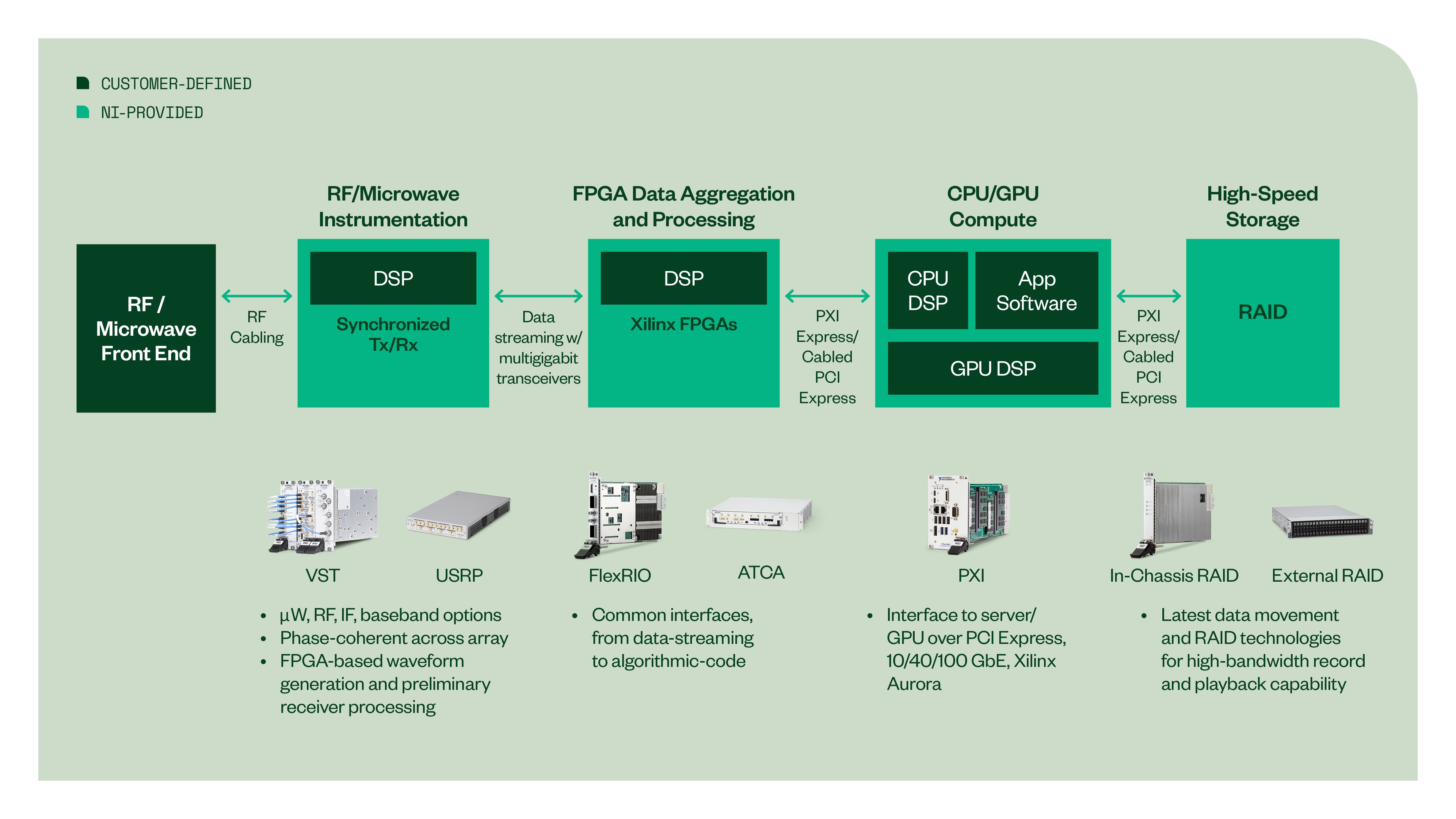
Using COTS hardware can ease the burden of building a testbed by providing the RF I/O, data aggregation and processing, streaming architectures, and storage out of the box. Let’s revisit the radar capability upgrades we discussed in the modeling and simulation section. In that case, the software-defined nature of NI USRP and PXI RF hardware makes it straightforward to alter transmission parameters, with frequencies ranging up to Ka band and bandwidths of up to 1 GHz. With heterogeneous processing options, you can deploy IP related to the new waveform at various points within the hardware. For FPGA-based waveform generation, or for preliminary receiver processing, the IP can sit close to the antenna, on the FPGA onboard the USRP or PXI hardware.

Furthermore, what if the next project is to take a waveform or algorithm and scale it from a single chain to a phased-array radar? Or to prove the value of moving from operator-controlled to cognitive radar? NI COTS components provide phase-coherent I/O by sharing local oscillators and reference clocks across multiple USRP devices, making them ideal for porting an algorithm from a single channel to a phased-array system. For cognitive radar, the ability to receive and process data inline and make decisions to adapt the radar output, while running knowledge-aided computing on GPUs, aligns to software-defined radar system architecture. This makes NI COTS components well-suited to cognitive radar prototyping.
Moving from Testbed to Mission Hardware
Ultimately, the goal is to transition novel technology to fielded capability. Once you’ve demonstrated and validated new techniques, you can hand-off IP to other teams, departments, or organizations for reuse—either within a hardware-in-the-loop validation architecture, or for mission hardware deployment, decreasing the cost of operational hardware development. Again, this can be time-consuming if you need to rewrite IP for deployment. To accelerate that process, NI has introduced the LabVIEW FPGA IP Export Utility. With this software add-on, you rapidly can prototype algorithms within LabVIEW FPGA, on COTS hardware built upon Xilinx FPGAs. Then, you can export validated designs as VHDL source code or netlists for use on any Xilinx Vivado device of the same family.
Conclusion
Ideas may be cheap, but as we have seen, determining whether they will work in practice is neither cheap nor simple. However, the right modeling, simulation, prototyping, and validation tools—plus the ability to migrate IP between those phases—significantly accelerates the process of proving out concepts.
Next Steps
