NI-9212 Getting Started
- Updated2022-08-31
- 5 minute(s) read
NI-9212 Getting Started
NI-9212 with TB-9212 Nomenclature
In this article, the TB-9212 with screw terminal and the TB-9212 with mini TC are referred to inclusively as the TB-9212. The information in this article applies to all versions of the TB-9212 unless otherwise specified.
NI-9212 Block Diagram

- Each channel simultaneously passes through a filtered, differential amplifier before being sampled by a 24-bit ADC.
- The NI-9212 provides channel-to-channel isolation.
Open Thermocouple Detection
Each channel has an open thermocouple detection (OTD) circuit, which consists of a current source between the TC+ and TC- terminals. If an open thermocouple is connected to the channel, the current source forces a full-scale voltage across the terminals.
Input Impedance
Each channel has a resistor that produces an input impedance between the TC and COM terminals. The gain and offset errors resulting from the source impedance of connected thermocouples are negligible for most applications. Thermocouples with a higher lead resistance can introduce more significant errors.
NI-9212 Timing Modes
The NI-9212 supports high-resolution, best 50 Hz rejection, best 60 Hz rejection, and high-speed timing modes.
Thermocouple Measurement Accuracy
Thermocouple measurement errors depend partly on the following factors.
- Type of thermocouple
- Accuracy of the thermocouple
- Temperature that you are measuring
- Resistance of the thermocouple wires
- Cold-junction temperature
NI-9212 Connection Guidelines
- Make sure that devices you connect to the NI-9212 are compatible with the module specifications.
- The shield grounding methodology can vary depending on the application.
- Refer to your thermocouple documentation or the thermocouple wire spool to determine which wire is the positive lead and which wire is the negative lead.
Minimizing Thermal Gradients
- Use small-gauge thermocouple wire. Smaller wire transfers less heat to or from the terminal junction.
- Run thermocouple wiring together near the TB-9212 to keep the wires at the same temperature.
- Avoid running thermocouple wires near hot or cold objects.
- Minimize adjacent heat sources and air flow across the terminals.
- Keep the ambient temperature as stable as possible.
- Make sure the NI-9212 terminals are facing forward or upward.
- Keep the NI-9212 in a stable and consistent orientation.
- Allow the thermal gradients to settle after a change in system power or in ambient temperature. A change in system power can happen when the system powers on, the system comes out of sleep mode, or you insert/remove modules.
- For the TB-9212 with screw terminal, use the foam pad in the opening, if possible, to restrict airflow around the terminals.
Connections with the TB-9212 with Screw Terminal
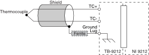
NI-9212 and TB-9212 with Screw Terminal Thermocouple Connection

TB-9212 with Screw Terminal Pinout

| Signal | Description |
|---|---|
| TC+ | Positive thermocouple connection |
| TC- | Negative thermocouple connection |
Wiring the TB-9212 with Screw Terminal
What to Use
- TB-9212 with screw terminal
- 0.05 mm2 to 0.5 mm2 (30 AWG to 20 AWG) wire with 5.1 mm (0.2 in.) of the inner insulation stripped and 51 mm (2.0 in.) of the outer insulation stripped
- Zip tie
- Screwdriver
What to Do

- Loosen the captive screws on the TB-9212 with screw terminal and remove the top cover and foam pad.
- Insert the stripped end of the wire fully into the appropriate terminal and tighten the screw for the terminal. Make sure no exposed wire extends past the screw terminal.
- Route the wire through the TB-9212 with screw terminal opening, remove slack from the wiring, and secure the wires using a zip tie.
- Replace the foam pad in the TB-9212 with screw terminal opening, reinstall the top cover, and tighten the captive screws.
Installing the TB-9212 with Screw Terminal
What to Use
- NI-9212
- TB-9212 with screw terminal
- Screwdriver
What to Do

- Connect the TB-9212 with screw terminal to the NI-9212 front connector.
- Tighten the jackscrews to a maximum torque of 0.4 N · m (3.6 lb · in.). Do not overtighten the jackscrews.
Connections with the TB-9212 with Mini TC
NI-9212 and TB-9212 with Mini TC Thermocouple Connection
TB-9212 with Mini TC Pinout

| Signal | Description |
|---|---|
| TC | Thermocouple connection |
Installing the TB-9212 with Mini TC
What to Use
- NI-9212
- TB-9212 with mini TC
- Screwdriver
What to Do

- Connect the TB-9212 with mini TC to the NI-9212 front connector.
- Tighten the jackscrews to a maximum torque of 0.4 N · m (3.6 lb · in.). Do not overtighten the jackscrews.
Connecting to the TB-9212 with Mini TC
What to Use
- TB-9212 with mini TC
- Shielded thermocouple
- Clamp-on ferrite bead (part number 781233-01)
What to Do
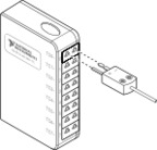
- Plug the thermocouple into the thermocouple input on the TB-9212 with mini TC.
- Install a clamp-on ferrite bead on the shield ground wire between the cable and the ground lug. You can use one ferrite bead per device for all cables.