PID (PID)
- Updated2025-01-28
- 6 minute(s) read
PID (PID)
Implements a single-precision floating-point PID algorithm for PID applications with high-speed control and/or high channel count on an FPGA target. You can use this VI to create single-channel, multi-channel, and multi-rate control applications.
The PID algorithm features control action range and uses an integrator anti-windup calculation to limit the effect of the integral action during transients. The PID algorithm also features bumpless controller output for PID gain changes.
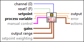
Inputs/Outputs
 channel (0)
—
channel (0)
—
channel specifies the channel that this VI processes. The valid value range is [0, 255]. The default is 0.  reset? (F)
—
reset? (F)
—
reset? specifies whether to reset the internal state of the channel that you specify. The default is FALSE.  setpoint
—
setpoint
—
setpoint specifies the value that you want process variable to attain. In equations that define the PID controller, SP represents setpoint.
process variable
—
process variable specifies the value of the variable that you want to control. In equations that define the PID controller, PV represents process variable.  manual control
—
manual control
—
manual control specifies the control mode and the control output value for the manual control mode.
 gains
—
gains
—
gains specifies the proportional gain, integral gain, derivative gain, and filter coefficient parameters of the controller. The proportional gain, integral gain, and derivative gain are normalized. Use the Convert PID Gains VI to convert PID gains into the form that gains requires.
output range
—
output range specifies the range for the control output value. If the control output value is outside output range, this VI coerces the value to fall within the range and returns the coerced value as the control output value. This VI implements integrator anti-windup when the control output is saturated at the specified minimum or maximum value.
setpoint weighting
—
setpoint weighting specifies corrections to apply to the error values of the controller. setpoint weighting tunes the proportional action and the derivative action.
 output
—
output
—
output returns the control output value of the PID algorithm.
error
—
error returns the difference between setpoint and process variable.  actions
—
actions
—
actions returns the values of the proportional action, the integral action, and the derivative action in the PID algorithm.
|
The PID VI calculates the output, u(k), according to the following equations:


where
Kp is proportional gain Ki is integral gain Kd is derivative gain a is filter coefficient SP is setpoint beta is proportional weighting PV is process variable gamma is derivative weightingExamples
Refer to the following example files included with LabVIEW FPGA Module.
- labview\examples\CompactRIO\FPGA Fundamentals\FPGA Math and Analysis\Floating-point PID\Multi-Channel PID\Multi-Channel PID.lvproj
- labview\examples\CompactRIO\FPGA Fundamentals\FPGA Math and Analysis\Floating-point PID\Multi-Rate PID\Multi-Rate PID.lvproj
- labview\examples\R Series\FPGA Fundamentals\FPGA Math and Analysis\Floating-point PID\Multi-Channel PID\Multi-Channel PID.lvproj
- labview\examples\R Series\FPGA Fundamentals\FPGA Math and Analysis\Floating-point PID\Multi-Rate PID\Multi-Rate PID.lvproj