Composing a Real HIL System with I/O Modules (Electric Motor Simulation Toolkit)
- Updated2023-02-21
- 3 minute(s) read
Composing a Real HIL System with I/O Modules (Electric Motor Simulation Toolkit)
In real hardware-in-the-loop (HIL) systems, the controller and simulator are usually on separate hardware. The I/O modules between the hardware connect the controller and simulator in a closed-loop.
In this step, you run the LabVIEW sample project wizard to create an Electric Motor Simulation sample project, in which you configure the I/O modules as well. Refer to the sample project documentation for information about connecting the controller, simulator, and I/O modules. You also can replace the control algorithm with your own code, run the solution, and verify the control algorithm.
Simulating on FPGA Targets
The following illustration describes a real HIL system where the simulator is on an FPGA target.
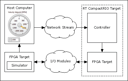
In a real HIL system, the simulator runs on an FPGA target and the controller runs on a real-time (RT) CompactRIO target. The host computer can be a desktop PC or a PXI target. If the host computer is a desktop PC, the FPGA target must run on a separate RT target. If the host computer is a PXI target, the FPGA target can either run on the host computer or a separate RT PXI target.
The following steps describe the workflow of an HIL system.
- On the host computer, you run a main VI which provides a user interface for you to specify the motor parameters, change the velocity setpoint, and monitor the motor state.
- The host computer sends commands, such as velocity setpoint changes, to the RT CompactRIO target through network stream.
- The controller reads motor status from the simulator and writes the control commands back to the simulator through I/O modules.
- The host computer reads the latest motor status directly from the simulator.
Simulating on Real-Time Targets
The following illustration describes a real HIL system where the simulator is on a real-time target.

In this HIL system, the simulator runs on an RT PXI target while the controller runs on an RT CompactRIO target. The following steps describe the workflow of electric motor simulation on RT targets.
- On the host computer, you run a main VI which provides a user interface for you to specify the motor parameters, change the velocity setpoint, and monitor the motor state.
- The host computer sends commands of velocity setpoint changes to the RT CompactRIO through network stream.
- The host computer sends commands of load torque changes to the RT PXI target through network stream.
- The controller reads motor status from the simulator and writes control commands back to the simulator through I/O modules.
- The host computer reads the latest motor status from the RT PXI target by using the shared variables.