Timing and Synchronization Systems
Contents
- Planning for Synchronization
- Physically Connected Systems
- Time-Referenced Systems
- Time Protocols
- Additional Resources
Planning for Synchronization
The two most important variables in designing a timing and synchronization scheme are synchronization precision and the distance between the system nodes. System designers must account for the limitations created by these variables because as transmission distance increases, it is more difficult to share signals between systems to keep them synchronized.
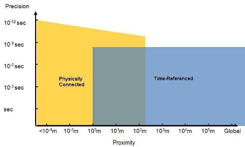
This trade-off between precision and distance presents a problem: to have a high precision of synchronization, you must have a clock with high frequency and accuracy, which can degrade as the distance between chassis, or nodes, increases. In most systems, you know the distances you must design for. You may have a single node, a group of nodes in one location, or multiple nodes that are spread out over a greater distance. Based on this, you must decide if you can successfully transmit the clock and trigger signals over this distance without too much degradation. If you cannot, then you must use a time reference to relay the clock domain information. Figure 1 shows the precision versus distance graph for physically connected and time-referenced synchronization systems.
Figure 1. Precision versus Distance Graph
The precision versus distance graph shows that as the distance between nodes increases past a certain point, you cannot physically connect the clock and trigger lines for each node together anymore. You need another method of conveying the clock and trigger signals from the master node to the other slave nodes in the system. This method, examined later in this tutorial, is called time-referenced synchronization.
Physically Connected Systems
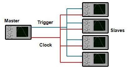
Now consider the yellow portion of the precision versus distance graph. This area represents the precision achievable by physically connected synchronization systems. Because the clock and trigger signals are physically connected with cables, they can achieve higher precision and are less vulnerable to clock signal problems, such as clock skew and clock drift, than the time-referenced systems discussed later. The operation of this type of synchronization system is fundamentally simple. The master node creates a clock and then shares that clock with all other nodes by means of cabling. When the action, such as data acquisition, is started on the master node, a trigger signal is shared with the other nodes to begin the action. Figure 2 shows an example of a physically connected system, along with the clock and trigger lines.
Figure 2. Physically Connected Synchronization System
Time-Referenced Systems
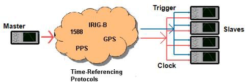
The blue portion of the precision versus distance graph shows the precision achievable by time-referenced synchronization. In a time-referenced system, protocols such as GPS are used to convey time information across greater distances than are possible with cabling. This time information is used by each system node to determine the present time and create a clock based on that reference. You can use a future time event, which is when an action starts after a defined time is reached, to trigger an action across all nodes simultaneously. Figure 3 shows a time-referenced synchronization system.
Figure 3. Time-Referenced Synchronization System
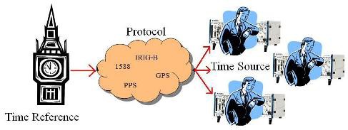
Another method of visualizing this transfer of time data via time protocols is the clock tower/wristwatch analogy. Think of the master node as being the clock tower and the slave nodes as being the people in a small town. Everyone in the town must be at work at 8:00 a.m. and they all have their own wristwatches. But each person’s wristwatch could be different, and there might be confusion over the correct current time. If each person looks at the clock tower and resets, or synchronizes, his or her wristwatch to the clock tower time reference, then everyone has the right time and arrives at work on time. The same conveyance of time information takes place in time-referenced systems.
Figure 4. Time Reference and Time Source
Time Protocols
Time protocols are the tools you use to transport time information across large distances.
Pulse per second (PPS) – PPS, the simplest form of synchronization, is a signal that outputs a high logic level once a second. It does not contain information about the specific time of day or year; it outputs a pulse only once a second. The pulse width is generally 100 ms, but many receivers allow the user to specify the pulse width, as long as it is less than one second. Figure 5 shows a PPS signal.
Figure 5. Pulse per Second
IRIG-B – This protocol is used to transmit time data. The signal is similar to PPS, but instead of a single pulse once a second, IRIG-B sends coded bits that make up a data frame that is one second long. This data frame presents time information in seconds, minutes, and days and provides a status byte. IRIG-B has a synchronization precision of tens of nanoseconds.
Figure 6 shows how time is sent using IRIG-B. The entire frame is only one second long. It is based on pulse-width modulation (PWM), where a 25 percent duty cycle represents a 0, a 50 percent duty cycle is a 1, and a 75 percent duty cycle is a Pause (P) to separate the pulses for seconds, minutes, days, and the status. Two pause cycles (R in this diagram) signify the end of a timestamp. Figure 6 shows an IRIG-B signal, which is read from right to left.
Figure 6. IRIG-B
IEEE 1588 – IEEE 1588 is a packet-based protocol that you can use over Ethernet. It defines a standard set of clock characteristics and value ranges for each characteristic. By running a distributed algorithm, called the best master clock (BMC) algorithm, each clock in the network identifies the highest-quality clock; that is the clock with the best set of characteristics.
The highest-ranking clock, called the “grandmaster” clock, synchronizes all other “slave” clocks. If the grandmaster clock is removed from the network, or if its characteristics change in such a way that it is no longer the “best” clock, the BMC algorithm helps participating clocks automatically determine the current best clock, which becomes the new grandmaster. This algorithm offers a fault-tolerant and administrative-free way of determining the clock used as the time source for the entire network.
The grandmaster clock periodically issues a “sync” packet containing a timestamp of the time when the packet left the grandmaster clock. The grandmaster may also issue a follow-up packet containing the timestamp for the sync packet. The use of a separate follow-up packet allows the grandmaster to accurately timestamp the sync packet on networks where the departure time of a packet cannot be known accurately beforehand.
Global positioning system (GPS) – GPS is a radio frequency encoded signal that provides time, position, and velocity information by means of a network of triangulation satellites. This time-reference signal, which is globally available, delivers synchronization precision between tens and hundreds of nanoseconds. To use this signal, you need a GPS antenna with a clear view of the sky.


