Using the RM-26999 with the ECU Test System (ECUTS)
Overview
The RM-26999 is a power signal conditioner that connects to a simultaneous-sampling multifunction I/O (SMIO) device for power measurements. It features four voltage input channels with peak voltages up to 2,000 V and four current transducer ports for current measurements. The current transducer ports are optimized for flux-gate transducers by providing all the power, communication, and signal lines required for accurate measurements. This document lays out considerations to observe when using the RM-26999 cabled to an Interchangeable Test Adapter (ITA) with the ECUTS-16000/16001.
Before continuing, please view the following notices:
Notice: The ECUTS has not been pre-qualified for high voltage signaling, whether through the mass interconnect or otherwise into the rack. Do not install the RM-26999 in the ECUTS-16000/ECUTS-16001 rack. Instead, mount the RM-26999 and route the low voltage signal cables to the ECUTS per the instructions in the RM-26999 User Manual.
Notice: Observe all safety considerations in the RM-26999 Safety, Environmental, and Regulatory Information document, the ECUTS-16000/16001 Safety, Environmental and Regulatory Information document, and the RM-26999 User Manual.
Note: To optimize signal integrity, mount the RM-26999 close to the device under test. This minimizes cable lengths of high voltage and high current signals.
Contents
- Required Documentation
- Required Hardware
- Required Software
- Power Considerations
- Connection Considerations
- Safety and EMC Considerations
Required Documentation
Observe all precautions, installation, and operating instructions in the following documents on ni.com/manuals:
- ECUTS-16000/16001 User Manual
- ECUTS-16000 Safety, Environmental and Regulatory Information
- ECUTS-16001 Safety, Environmental and Regulatory Information
- ECUTS-16000 Specifications
- ECUTS-16001 Specifications
- RM-26999 Safety, Environmental and Regulatory Information
- RM-26999 Specifications
- RM-26999 User Manual
- X Series User Manual
Refer to the DaniSense Product Manual for DCCTs families on danisense.com for details on the current transducers.
Refer to the Virginia Panel Corporation Assembly, Installation, and Removal of Contacts and Modules for QuadraPaddle Signal Contacts and Modules on vpc.com for details on the QuadraPaddle ITA PCB adapter.
Required Hardware
Each RM-26999 connects to a PXI multifunction I/O module in the ECUTS. NI recommends the PXIe-6366. The PXIe-6386 may also be used if the acquisition requires a sample rate higher than 2 MS/s.
Required Software
Install the RM-26999 software package from the VI Package Manager to interface with the RM-26999 from LabVIEW. The ECU Test System Software Suite includes the NI software required to work with the RM-26999 with the RM-26999 software package. Refer to the RM-26999 User Manual for more information about the RM-26999 software package and installation instructions.
Power Considerations
The RM-26999 derives power from an external 24V power supply and the 5V user supply present on the SMIO device it connects to. A large portion of the power derived from the 24V supply is used to supply the current transducers. The RM-26999 is rated to draw up to 150W from the 24V source.
Single RM-26999 Signal Conditioner
If you use any of the current transducers listed in Figure 1 for all four ports on a single RM-26999, the RM-26999 will not draw more than 30W from the 24V power supply. Use the 24V, 48W power supply provided by the ECUTS through pins 34 and 35 on the J22 slot for powering a single RM-26999 if that power supply meets the overall ITA 24V rail power budget. NI recommends the DaniSense Voltage Output Current Transducers available through NI.
Figure 1: DaniSense Voltage Output Current Transducers. Source: RM-26999 User Manual.
Multiple RM-26999 Signal Conditioners
An ECUTS may connect to up to four RM-26999 devices, provided the ECUTS contains one SMIO for each RM-26999. The ECUTS 24 V, 48 W power supply is insufficient for use with more than one RM-26999. Supply additional 24 V power to each RM-26999 using an additional power supply. Ensure that the power rating of this additional power supply is sufficient to meet your application’s needs.
Connection Considerations
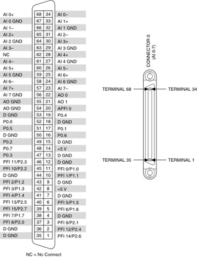
Connect the RM-26999 to the SMIO device in the ECUTS-16000/16001 through the J18-J21 slots. NI recommends using a PCB QuadraPaddle adapter (Virginia Panel Corporation part number 510151121) and routing the SMIO device to a VHDCI connector (NI part number 785633-01). Figure 2 shows the relevant portion of the ECUTS pin map that corresponds to the SMIO. Figure 3 shows the VHDCI pinout.
Figure 2: SMIO QuadraPaddle Pinout (VHDCI Pin Numbers). Source: ECUTS-16000/16001 User Manual.
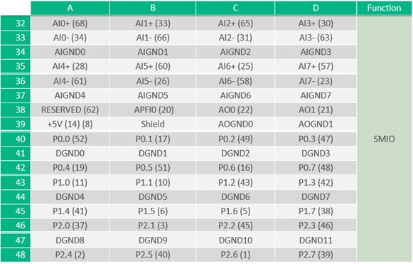
Figure 3: NI 6366/6386 VHDCI Pinout. Source: X Series User Manual.
Observe the following recommendations for the PCB adapter layout:
- Tie and route the AIGND0 – AIGND7 pins as one plane to the VHDCI AI 0 GND – AI 7 GND.
- Tie and route the AOGND0 – AOGND1 pins as one plane to the VHDCI AO GNDs.
- Tie and route the DGND0 – DGND11 pins as one plane to the VHDCI D GNDs.
- Route the Shield pin to the shield of the VHDCI connector.
- Route the 5V lines with traces capable of carrying 1A.
- Route the Analog Input channels as differential signals over the AIGND plane.
- Route the Analog Output channels as single ended signals referencing the AOGND plane.
- Route the Digital IO lines as single ended traces with a 50-ohm characteristic impedance with respect to the DGND plane.
- Refer to Virginia Panel Corporation’s User Manual for the QuadraPaddle on vpc.com for the recommended PCB footprint.
Safety and EMC Considerations
Notice: Follow all the indications provided in the RM-26999 Safety, Environmental, and Regulatory Information document and the RM-26999 User Manual.
The RM-26999 can generate high voltage and current measurements which require special considerations:
- The RM-26999 must be connected to a separate protective earth ground. The chassis ground pin located on the J22 slot of the ECUTS is not a protective earth ground and must not be used as such.
- If using the PCB adapter, enclose the RM-26999 and the PCB adapter in a properly shielded enclosure to ensure EMC compliance.
- Use the cabling recommended in the RM-26999 User Manual to ensure EMC Compliance.
- All persons involved with planning, installing, connecting, or configuring software and hardware for use in systems that employ the RM-26999 must meet the minimum required competency requirements listed in the RM-26999 User Manual.
Information is subject to change without notice. Refer to the NI Trademarks and Logo Guidelines at ni.com/trademarks for information on NI trademarks. Other product and company names mentioned herein are trademarks or trade names of their respective companies. NI MAKES NO EXPRESS OR IMPLIED WARRANTIES AS TO THE ACCURACY OF THE INFORMATION CONTAINED HEREIN AND SHALL NOT BE LIABLE FOR ANY ERRORS. © 2021 National Instruments Corporation. All rights reserved.