Using the SLSC-12251/2 Fault Insertion and Current Sensing Unit with VeriStand
Contents
- Introduction
- Using the SLSC-12251/2 for Signal Faulting
- Adding Current Measurement
- Adding Digital Pulse Time Measurement Using the SLSC-12201
- Controlling the SLSC-12201 and SLSC-12251/2 from VeriStand
- Measuring the Line Currents on the SLSC-1251/2
- Applying Faults to the Signals
- Hardware Components
- Additional Resources
Introduction
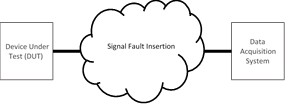
When testing Embedded Software on mission critical Electronic Control Units, like those used in Automobiles or Aircraft, it is important to validate the behavior with external faults for example if the integrity of the signals to the controller are compromised. The SLSC-12251/2 products from NI are designed for this purpose, these modules can be inserted into the signal path between the Data Acquisition System and the Device Under Test (DUT).
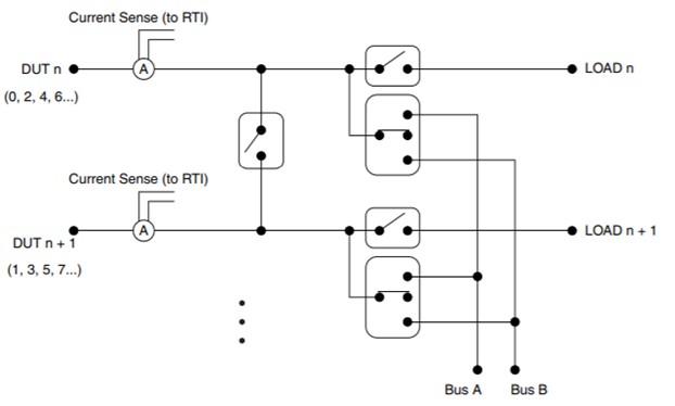
During a mission an Electronic Control Unit may be exposed to erroneous signals due to fracturing of the wiring harnesses. This can be caused due to fatigue, mechanical failure, accidental or deliberate damage during operation. The SLSC-12251/2 is capable of presenting the DUT with the following errors: open circuit, pin shorted to two different potentials (for example Vbatt or GND) and short to another pin.
The SLSC-12251/2 modules provide current sensing on each channel when coupled with a measurement module in a Data Acquisition System. This functionality can be used to measure current profiles for example measuring the profile of a solenoid injector.
Figure 1: SLSC-12251/2 Module Functionality
| Feature | SLSC-12251 | SLSC-12252 |
| Channel Count | 16 | 8 |
| Maximum Current (per channel) | 8A continuous RMS | 30 A continuous RMS |
| Maximum Current (per module) | 56 A continuous RMS | 60 A continuous RMS |
| Maximum Current (pulsed per channel) | 29 A peak for 1 ms | 88 A peak for 1 ms |
| Maximum Voltage | 100 V | 100 V |
| Relay Type | FET | FET |
| Current Measurement Accuracy | 1.11% (8 A) | 1.11% (30 A) |
Table 1: SLSC-12251/2 Features
Reading the SLSC-12251/2 current with a DAQ card in VeriStand
Information on this can be found in the following two sections of the article:
Other information can be found in following sections of the manual:
Using the SLSC-12251/2 for Signal Faulting
The primary purpose of the SLSC-12251/2 modules is to create faults on high current signals. The modules can be connected directly to the DUT using a custom cable or they can couple to a custom break out box or mass termination interface.
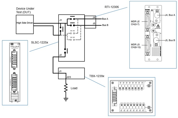
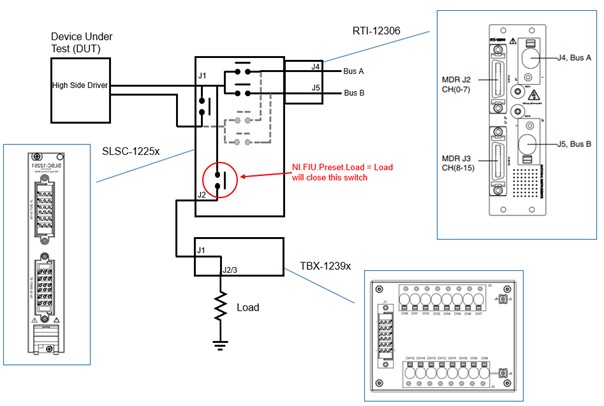
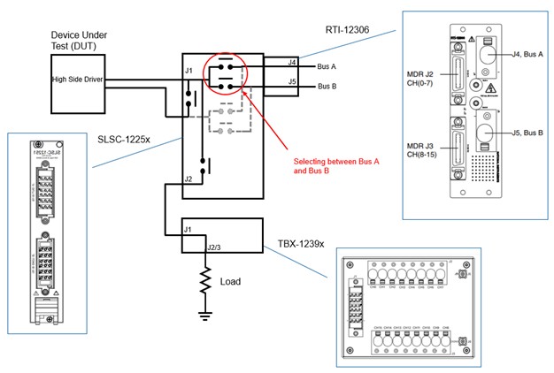
The signal passes through the module, where the fault can be inserted by switching certain relays, and then couples to a load using either a custom load box or and standard terminal block (TBX-1239x). The SLSC-12251/2 requires an RTI-12306 for connecting to the fault busses. The diagram below shows the signal path from the DUT through to a load, the relays are controlled via the SLSC bus using software. More information on the software is described in the software section.
Figure 2: Signal Fault
The Fault Insertion Modules can be used to create the following fault scenarios:
• Open-circuit
• Short-circuit to Bus A
• Short-circuit to Bus B
• Differential signal short-circuit
Current limitations:
• SLSC-12251 - 16 channels at 8A Continuous RMS (29 A peak for 1 ms)
• SLSC-12252 - 8 channels at 30A continuous RMS (88 A peak for 1 ms)
For more information please refer to the module specifications, a link to these is available in Section 7 of this paper.
The load shown in figure 2 may be a real load for example a motor or solenoid, or it may be a dummy load representing a real load.
Adding Current Measurement
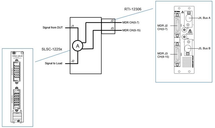
The SLSC-12251/2 modules have current sense capability on each channel, these sense values are available as uncalibrated differential voltages. Calibration coefficients are stored for each channel on the module and these coefficients can be accessed via software.
The diagram in Figure 2 shows the signal path for current measurement. Each signal which passes through the SLSC-12251/2 passes through a current to voltage transducer and is made available at the RTI for measurement.
Figure 3: Current Sense
The differential voltages signals can be connected to a measurement system for example an NI PXI DAQ card or NI PXI R series card using a compatible cable (SHC68-4MDR26-AI32, SHC68-3MDR26-RMIO).
Adding Digital Pulse Time Measurement Using the SLSC-12201
If it is required to measure the Digital Time of a pulse through the load (Pulse Width Modulation) the user should select the required terminal block.
• SLSC-12251 for pulse measurement use the TBX-12397*
• SLSC-12252 for pulse measurement use the TBX-12399*
*Please note that it is important to use the device within its specified ranges to ensure safety of the users and system.
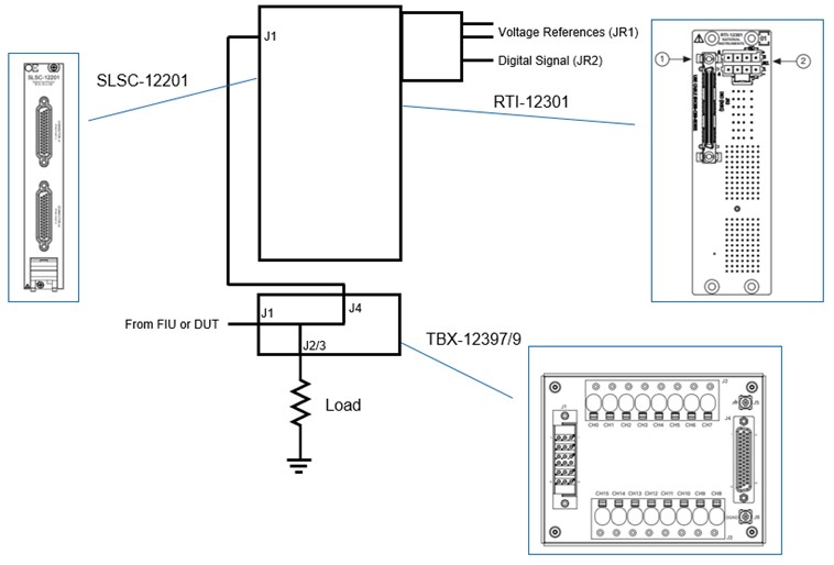
The TBX-12297/9 can be connected to the SLSC-12201 using a compatible HD44 to HD44 cable. Using the SLSC-12201 as an input the user can then set thresholds to distinguish between high and low signals for pulse measurement. The SLSC-12201 connects to an NI R Series (RDIO2) using and RTI-12301 and an NI RDIO2 cable. This setup is shown in Figure 4.
For more information on pulse measurement please refer to Using The SLSC Architecture To Add Additional Elements To The Signal Path Of A Test System.
Figure 4: Using a TBX-1397/9 with an SLSC-12201
Controlling the SLSC-12201 and SLSC-12251/2 from VeriStand
System Setup
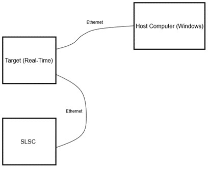
Figure 5: System Setup
For this white paper we will use VeriStand as the software which will interact with the SLSC. To do this user will need to install VeriStand on the Host Computer and the Target. The host, target and SLSC maybe on the same network or separate networks as shown in figure 4.
For this section we will first describe using the SLSC-12201 Plugin Custom Device.
Using the SLSC-12201 Plugin Custom Device
To use the SLSC-12201 module in VeriStand, the user will need to install an SLSC plugin custom device on the system.
SLSC-12201 Custom Device example.
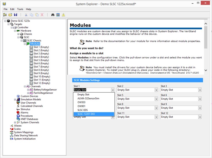
After the plugin is installed, the user should see the adapter SLSC plugin:
Figure 6: Using the SLSC-12201 Custom Device in VeriStand
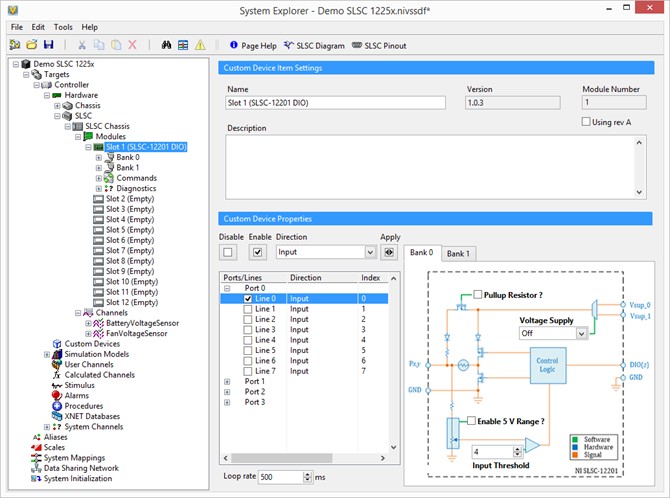
SLSC-12201 Plugin allows the user to configure the digital lines on the SLSC-12201 as inputs or outputs. In this case the user should configure the lines as inputs and specify a threshold from 4 V with the range going up to 27.5 V and should correspond to the external reference.
Figure 7: Configuring the SLSC-12201
The line signals should be connected to a compatible R series module as described in section 4. The R series module can be programmed to measurement the pulse signal timing. For more information see Using The SLSC Architecture To Add Additional Elements To The Signal Path of a Test System.
Using the SLSC Electronic Datasheet Custom Device
Since the SLSC-12251/2 are more simple devices the user can download and use the SLSC Electronic Sheet Plugin Custom Device (EDS). This is a generic SLSC Module Custom Device which reads the module capabilities of any SLSC module and provides the user with a simple user interface for communicating with the module parameters.
The following screenshot show how you can use the SLSC EDS Plugin Custom Device to access an SLSC-12251/2
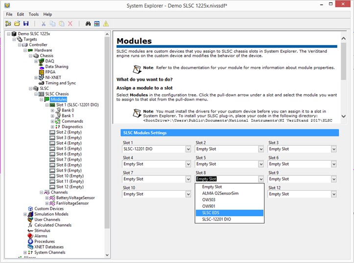
Figure 8: Assigning Plugin Custom Devices to a Slot in the SLSC
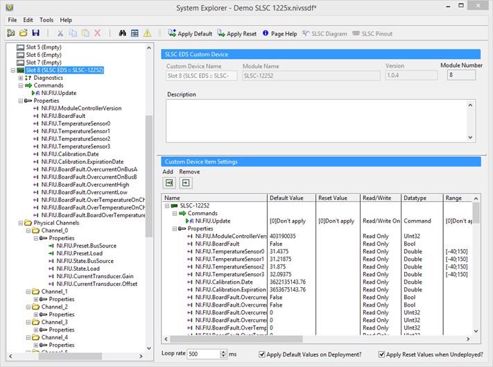
Firstly, the user should allocate which slots in the SLSC will use the SLSC EDS Custom Device. The SLSC EDS Custom Device with then read the capability file stored on the SLSC modules, in this case the SLSC-12251/2, and will populate the tree with the module properties and channels as shown below.
Figure 9: Configuring the SLSC-12251/2 to connect to a load on deployment
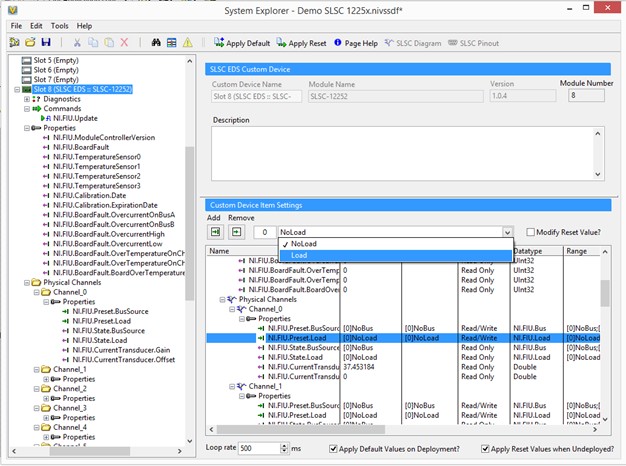
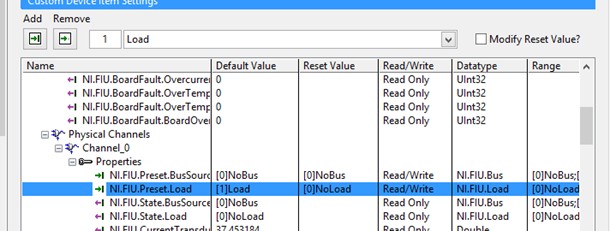
The user can then configure the SLSC-12251/2 to connect lines through FIU to the load by changing the “NI.FIU.Preset.Load” from “NoLoad” to “Load”. Once the system deploys it will then automatically connect to the load and will disconnect from the load when the system undeploys.
Figure 10: Connecting to a load on deployment
Figure 11: Configuring the state of the load relay after undeploy
The SLSC-12251/2 can be configured to maintain the same state after undeploy setting the “Modify Reset Value?” to “Load”. Care should be taken to ensure that the system is safe since under these conditions.
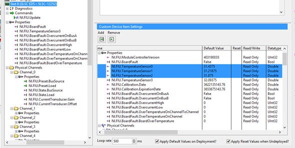
Figure 12: SLSC-12251/2 Temperature Sensors
The SLSC-12251/2 has 4 temperature sensors and these can be used to read the temperature at different 4 quadrants of the module (see the SLSC-12251/2 User Manual for more information on placement of the temperature sensors). These channels, and other channels, are available for monitoring during operation however you can remove channels which will not be required by selecting the property and clicking on remove.
Figure 13: Removing channels from properties
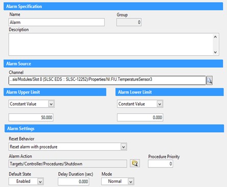
The screenshot below shows how you can specify Alarms on a channel. In this case, an Alarm is generated when the maximum temperature reaches or exceeds 50 degrees Celsius.
Measuring the Line Currents on the SLSC-1251/2
To measure the current from the current transducers on the SLSC-12251/2 the user will need to connect to a DAQ device using a compatible cable as described in Section 3. In this example we are using a PXIe-6355 DAQ device.
Figure 15: Configuring a DAQ card to measure the line current
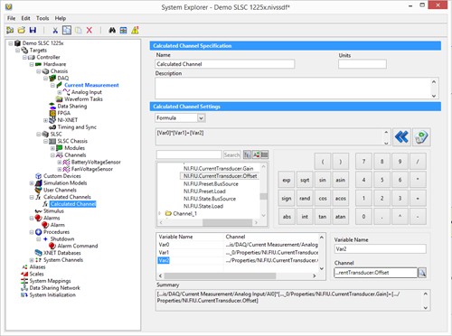
Calculated Channels can be used to convert the voltage measured by the DAQ card to current by using the Gain and Offset channels stored for each channel on the module.
Figure 16: Using calculated channels to measure the line current
Applying Faults to the Signals
The user can choose to fault the lines to Bus A or Bus B by switching the relays shown in Figure 17. Care should be taken to ensure that the system is safe, this may mean the Load relay should be disconnected before enabling a fault condition.
Figure 17: Selecting Bus A or Bus B for faulting
The following screenshots show how to set and reset the Bus A and Bus B relays.
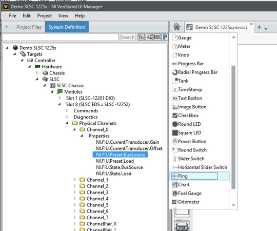
Figure 18: Mapping Properties to Bus A or Bus B
Selecting the NI.FIU.Preset.BusSource will allow the user to map this to open, Bus A or Bus B.
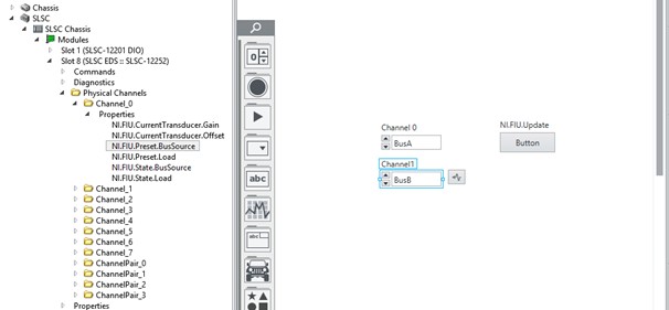
Figure 19: Activating Relays
The NI.FIU.Update should also be mapped to a button, the values will only be updated when this button is activated.
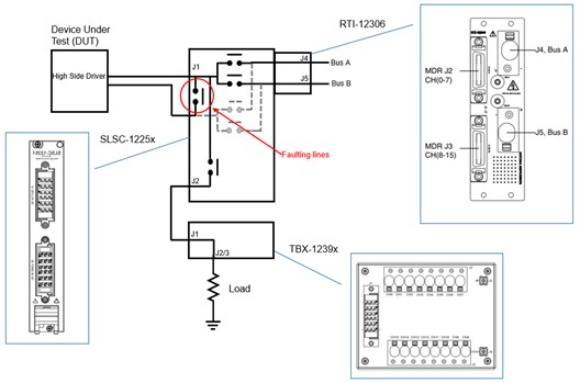
The SLSC-12251/2 can fault channel lines in a differential manner, that is, Line 0 to Line 1, Line 2 to Line 3 and so on.
Figure 20: Faulting between lines
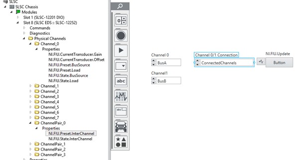
To activate the relay between Channel 0 and 1 use the ChannelPair Properties.
Figure 21: Setting ChannelPair Properties
The NI.FIU.Update button should be activated to apply the changes.
Hardware Components
| Model Name | Description | Part Number | |
| SLSC Modules | |||
|---|---|---|---|
| SLSC-12251 | SLSC-12251 Fault Insertion Module, 16 CH, 8 Amp | 786444-01 | |
| SLSC-12252 | SLSC-12252 Fault Insertion Module, 8 CH, 30 Amps | 786445-01 | |
| SLSC-12201 | SLSC-12201 33V DIO module with thresholding (NI) | 785356-01 | |
| RTI's | |||
| RTI-12306 | RTI-12306 FIU 16 AI FOR 38MDR | 785378-01 | |
| RTI-12301 | RTI DIO 32 FOR SHC68-C68-RDIO2 REV 2 | 786330-01 | |
| Terminal Blocks | |||
| TB-12396 | TB-12396 8 amp connector with no DIO connector (8A, HV) | 786640-01 | |
| TB-12397 | TB-12397 8 amp connector with DIO connector (8A, LV) | 786639-01 | |
| TB-12398 | TB–12398 30 amp connector with no DIO connector (30A, HV) | 786638-01 | |
| TB-12399 | TB-12399 30 amp connector with DIO connector (30A, LV) | 786446-01 | |
| High Current Signal Cables | |||
| SP18M TO SP18F, 1M ---- 16ch, 8A | 147945-01 | ||
| SP8M TO SP8F, 1M --- 8ch, 30A | 148299-01 | ||
| Measurement Cables | |||
| SHC68-4MDR26-AI32 | 148707-01 | ||
| SHC68-2MDR26-EPM | 148708-01 | ||
| SHC68-3MDR26-RMIO | 148312-01 | ||
| SHC68-2MDR26-RDIO2 | 148709-01 | ||
| SHC68-C68-RDIO2 (1m) | 156166-01 | ||
Additional Resources
- SLSC-12251/2 User Manual
- SLSC-12251 Specifications
- SLSC-12252 Specifications
- SLSC-12201 Specifications
- SLSC-12201 User Manual
- RTI-12301 Getting Started Guide
- Using The SLSC Architecture To Add Additional Elements To The Signal Path Of A Test System
- Save Time and Maximize Reuse in HIL Testing with the SLSC Extension for PXI and CompactRIO
