The NI-CAN Channel API
Overview
This document describes the basics of the Channel API for NI-CAN driver software. It is useful for engineers just getting started with NI-CAN 2.0 and higher. For a full overview of the software, please view the NI-CAN Hardware and Software User Manual.
NI-CAN is compatible with versions of LabVIEW up to LabVIEW 2018, for users using later LabVIEW versions, please review the guide to Migrating NI-CAN Applications to NI-XNET.
Contents
- Introduction
- Channel Configuration
- Importing Channels from a Database File
- Creating Channels in Measurement & Automation Explorer
- Channel API Functions
- CAN Init Start
- CAN Read
- CAN Write
- CAN Clear
- Additional Channel API Functions
Introduction
The NI-CAN driver software provides 2 full-featured Application Programming Interfaces (APIs) in addition to tools for configuration and analysis within NI Measurement & Automation Explorer (MAX). The NI-CAN APIs enable you to develop applications that are customized to your test and simulation requirements. With the Channel API, you can use high-level, easy-to-use functions for access to CAN channels defined in Vector database (.dbc) or NI CAN database (.ncd) files. The Channel API is recommended for beginners to CAN. The Frame API provides low-level access to the bits transmitted over the CAN bus and is recommended for advanced users. This document focuses on the Channel API. For more information on the Frame API, see the NI-CAN Hardware and Software Manual.
The NI-CAN Channel API takes advantage of predefined CAN channels to make CAN programming similar to NI-DAQ programming. The basic programming model for the Channel API is shown in Figure 1.
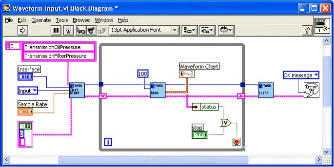
Figure 1 Basic NI-CAN Channel API programming model in LabVIEW
Channel Configuration
First, the CAN channels must be defined or imported. This can be done using Measurement & Automation Explorer (MAX), a configuration-based utility used to install, test, and configure the majority of NI hardware, including CAN interfaces. MAX can also be used to import or create CAN database files and includes additional tools such as the CAN bus monitor and CAN channel test panels.
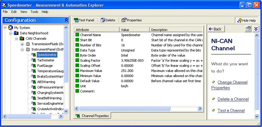
Figure 2 CAN Channels in Measurement & Automation Explorer
Importing Channels from a Database File
Often it is desirable to import CAN Channels from database files. To import CAN Channels from a Vector database (.dbc) file, expand the Data Neighborhood tree to see CAN Channels. Right click on CAN Channels and select Import from CANdb file. These database files are often created by the engineers that design the CAN devices. Now navigate until the desired database file is found. Once the file is found and selected, you may choose to import all messages in the file or you may select specific channels to import. Click the Import button and then click Done. The Messages and Channels will now appear in MAX under CAN Channels as shown in Figure 2. These messages and channels can be viewed and edited by expanding the message tree, right clicking on the desired channel and go to properties. By viewing the properties of a channel, you can see the location of the channel within the message in the message grid.
Creating Channels in Measurement & Automation Explorer
Sometimes you may not have a Vector database file available and will need to create the channels in MAX. Begin by right clicking on CAN Channels and selecting Create Message. Specify the name, arbitration ID, number of data bytes, and default interface, then select OK. Now individual channels are created by right clicking on the message and choosing Create Channel. You should specify the channel name, start bit, number of bits, scaling information, and units. Notice that as you specify the start bits and number of bits, the grid in the bottom right shows the location of the channel within the message.
Once you click OK, the channel will show up in MAX under the Message. To create another channel, right click again on the message and choose Create Channel. This time, notice that the grid has highlighted the bits that you reserved for the previous channel. If you try to configure another channel for the same bits, you will see a red error indicator. The remaining steps are the same for creating channels to complete the message. You can configure the message with a combination of analog and digital channels; you can use up to 64 digital channels of 1 bit each.
Once you have a desired channel configuration you can save it for use on other computers. Right click on CAN Channels and select Save Channel Configuration. This saves the configuration as a NI CAN database (.ncd) file which can be imported into MAX or called directly from your application using NI-CAN 2.0 or later driver software. As previously demonstrated with Vector database (.dbc) files, you can also import National Instrument database (.ncd) files into MAX from a saved configuration. To do this, right click on CAN Channels and select Load Channel Configuration, navigate to the .ncd file and select the desired messages. Choose Load and then click Done, the channels now once again appear in MAX.
Channel API Functions
The basic NI-CAN program consists of an Initialization, Read or Write, and a Clear (see Figure 1). The link between the functions is the Task. A CAN Task is a collection of CAN Channels that have the same timing and communication direction (read/write). A task can encompass several Messages, but they must all be on the same interface (port). This programming model is the same whether you are working in LabVIEW, LabWindows/CVI, C/C++, or Visual Basic 6.0. For a tutorial on LabVIEW please go to ni.com/tutorials.
CAN Init Start
CAN Init Start VI: The CAN Init Start function initializes a list of channels as a single task and starts communication for that task. The CAN Init Start function uses the following input parameters:
channel list—Specifies the list of channels for the task
interface—Specifies the CAN interface (CAN0, CAN1, etc.) to use for the task.
mode—Specifies the I/O mode (direction of data transfer) to use for the task.
sample rate—Specifies the rate of sampling (samples per second) for data transfer
CAN Read
Multiple read modes make it easier to customize your application. There are 3 modes for read in NI-CAN. Each will be discussed in the following sections:
1. Single point
2. Continuous
3. Time-stamped
If the mode of Init Start is Input, your application must call the Read function to obtain samples. Your application typically calls Read in a loop until done. The Read function is CAN Read in LabVIEW (all types that don’t end in Time & Dbl) and nctRead in other languages. The behavior of Read depends on the initialized sample rate:
CAN Read VI:
Single point Read (Mode = Input, sample rate = 0)
This read returns a single sample from the most recent message(s) received from the network. One sample is returned for every channel in the Init Start list. It is most useful when you want fast access to the most recent CAN Message.
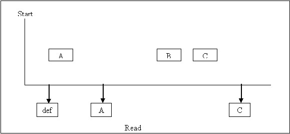
Figure 3 shows an example of Read with sample rate = 0. A, B, and C represent messages for the initialized channels. If no message is received since the start of the application, the Default Value in MAX (def) is returned, along with a warning.
Continuous Read (Mode = Input, sample rate > 0)
Continuous mode is useful when you want to log data alongside analog or digital data from a DAQ device. This read returns an array of samples for every channel in the Init Start list. Each time the specified time passes, a sample from the most recent message(s) is inserted into the arrays. In other words, the samples are repeated in the array at the specified rate until a new message is received. Continuous mode is useful when you want to log data alongside analog or digital data from a DAQ device. By using the same sample rate with NI-DAQ Analog Input channels, you can compare CAN and DAQ samples over time.
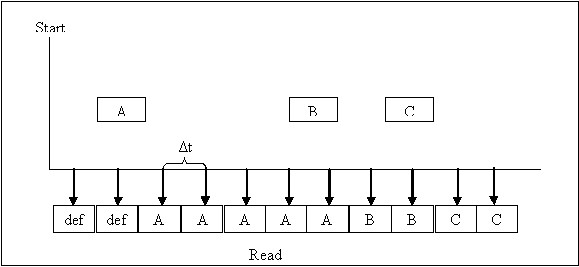
Figure 4 shows an example of Read with sample rate > 0. A, B, and C represent messages for the initialized channels. Δt represents the time between samples as specified by the sample rate. def represents the Default Value in MAX.
Timestamped Read (Mode = Timestamped Input)
Timestamped mode is useful for test applications where CAN/DAQ synchronization is needed, but there is no need for further CAN data processing. If the Init Start mode is Timestamped Input, your application must call the Read Timestamped function to obtain values. Your application typically calls Read Timestamped in a loop until done. The Read Timestamped function returns samples that correspond to messages received from network. For each message, an associated sample is returned along with a timestamp that specifies when the message arrived. An array of timestamped samples is returned for every channel in the InitStart list. The Read Timestamped function is CAN Read in LabVIEW (types that end in Time & Dbl) and nctReadTimestamped in other languages.
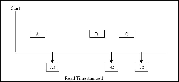
Figure 5 shows an example of Read Timestamped. A, B, and C represent messages for the initialized channels. At,Bt,and Ct represent the times when each message was received.
CAN Write
Multiple write modes make it easier to customize your application. There are 3 modes for write in NI-CAN. Each will be discussed in the following section:
1. Single point
2. Continuous
3. Time-stamped
If the Init Start mode is Output (or Output Recent), your application must call the Write function to output values. Your application typically calls Write in a loop until done. The Write function is CAN Write in LabVIEW and nctWrite in other languages. The behavior of Write depends on the initialized sample rate:
CAN Write VI
Non-Periodic Single Point Write (Mode = output, sample rate = 0)
Write transmits a message immediately on the network. The samples provided to write are used to form the message data bytes. One sample must be specified for every channel in the Init Start list. The Init Start mode must be Output for this behavior (not Output Recent). Figure 6 shows an example of Write with sample rate = 0. A, B, C and D represent messages for the initialized channels. For each Write, the associated messages are transmitted as quickly as possible.
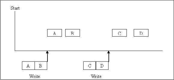
Figure 6. Example of Write with sample rate = 0
Continuous Write (Mode = output, sample rate > 0)
You provide an array of samples for every channel in the Init Start list. Each time specified time passes, the next message is transmitted. Each message uses the next sample from the array(s) to form the message’s data bytes. In other words, the samples from the array are transmitted periodically onto the network. By using the same sample rate with NI-DAQ Analog Output channels, you can output simultaneous CAN and DAQ samples over time.
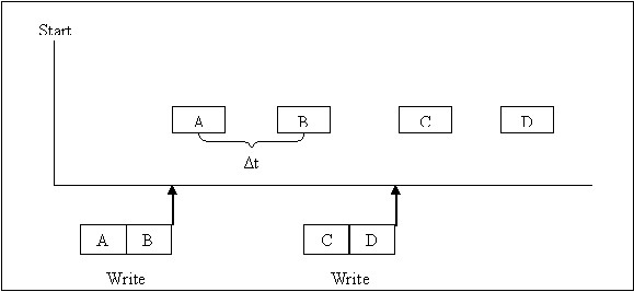
Figure 7 shows an example of Write with sample rate > 0 and Output mode. A, B, C and D represent messages for the initialized channels. Δt represents the time between message transmission as specified by the sample rate.
Single Point Write (Mode = Output Recent, sample rate > 0, You provide a single sample for every channel in the Init Start list. Each time the clock ticks at the specified rate, the next message is transmitted using the most recent sample that you provided. The Output Recent mode is useful when you have multiple tasks running at different rates, because you can write samples for all tasks in a single loop. Figure 8 shows an example of Write with sample rate > 0 and Output Recent mode.
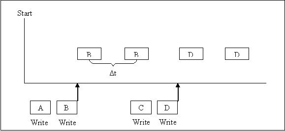
Figure 8. Example of Write with sample rate > 0, Output Recent Mode
CAN Clear
CAN Clear VI: The Clear function stops communication for the task and clears the configuration. For every task that you initialize, you must call Clear prior to exiting your application. The Clear function is CAN Clear in LabVIEW and nctClear in other languages.
Additional Channel API Functions
The following sections provide information you can use to extend the basic programming model.
Get Names
If you are developing an application that another person will use, you may not want to specify a fixed channel list in your application. Ideally, you want your end-user to select the channels of interest from user interface controls, such as list boxes. The Get Names function queries MAX or a CAN database and returns a list of all channels or messages in that database. You can use this list to populate user-interface controls. You can then select channels from these controls, avoiding the need to type each name using the keyboard. Once selections are made, your application can pass the resulting list to Init Start. The Get Names function is CAN Get Names in LabVIEW and nctGetNames in other languages.
Synchronization
The NI-CAN Channel API uses RTSI to synchronize specific functional units on each card. For CAN cards, the functional unit is the interface (port). For DAQ cards, the functional unit is a specific measurement such as Analog Input or Analog Output. Each function routes two signals over the RTSI connection:
· timebase—Specifies a common clock shared by multiple cards to prevent clock drift.
· start trigger—Specifies the start signal sent from one board to another to prevent start latencies
Set Property
This function allows you to set properties of the network including baud rate, transceiver type, and filter mode. The Init Start function uses interface and channel configuration as specified in MAX or the CAN database file. If you need to change this configuration within your application, you cannot use Init Start, because most properties cannot be changed while the task is running. Instead, use Init first, then set the property and start the task.
Get Property
This function allows you to get the properties of your channels, messages, or network including baud rate, message ID, and channel scaling factor.
For more information on the Channel API or the Frame API, download the NI-CAN Hardware and Software Manual and Specifications from ni.com/manuals.
Related Links:
NI Controller Area Network (CAN) Homepage
Synchronizing CAN and Analog Signals for Device Validation


