China Steel Prevents Downtime with Condition Monitoring and Diagnostics System Based on NI Technologies
Dr. Zhizhong Wang, China Steel Corporation Iron and Steel R&D Department
"The software and hardware environment need for fast, convenient, and stable system development is indispensable, and NI has it all."
- Dr. Zhizhong Wang, China Steel Corporation Iron and Steel R&D Department
The Challenge:
Preventing costly equipment failures and downtime by more closely monitoring the China Steel facility.
The Solution:
Developing a smart, problem-oriented analysis system that uses the Internet of Things (IoT) to remotely monitor the facility in real time, quickly convert large amounts of data to facility management, and immediately detect facility abnormities. The system must also improve overall facility efficiency, save energy, reduce carbon emissions, and enhance work place safety.
Author(s):
Dr. Zhizhong Wang - China Steel Corporation Iron and Steel R&D Department
柯忠和 專案工程師 - 中國鋼鐵公司
李仙家 工程師 - 中國鋼鐵公司
林智賢 工程師 - 中龍鋼鐵公司
黃永立 工程師 - 中龍鋼鐵公司
陳鴻飛 課長 - 中鴻鋼鐵公司
林銓亮 技術人員 - 中鴻鋼鐵公司
王嘉勝 工程師 - 中鴻鋼鐵公司
Our Motivation
China Steel Corporation (CSC) is the largest integrated steel maker in Taiwan. Our goal is to enhance facility maintenance and management efficiency. First and foremost, to achieve this goal we know we need to understand the tradeoffs between the set-up costs of machine condition monitoring (MCM) devices and the losses we experience due to unexpected faults. We also need to consider the critical pieces of equipment we own and the degree of difficulty involved in maintaining them. Effective MCM can help maintenance managers understand the condition of critical equipment in real time, which is a competitive advantage for steel manufacturers.
Our first self-developed facility online monitoring and diagnosis system (FOMOS) was installed on the CSC production line in 1998. The system performed well for monitoring certain issues such as mill vibrations, but after a few years the system became less reliable. We found that the hardware and software had limited functionality. We knew we could build a smarter, more connected system that could use the latest advances in processing power, wireless networks, and software connectivity. We realized that it was fairly easy to develop an MCM system, but it was difficult to address specific challenges we faced.
Our Challenge
Our biggest challenge to address was how to detect equipment abnormalities at an early stage without creating a large number of false alarms. Since vibration is a relative condition indicator and strongly affected by system or structural dynamic rigidity and transmissibility, in real situations, it is common to find that two pieces of the same equipment at similar locations and operating conditions exhibit different vibration levels after several years of operation. Figure 1 shows this phenomenon with two identical cooling fans under normal operating status. Vibration signals can be a key indicator for information such as wear, imbalance, misalignment, impact load, and bearing fault by using different signal processing and algorithms.
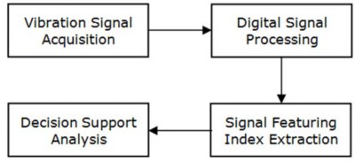
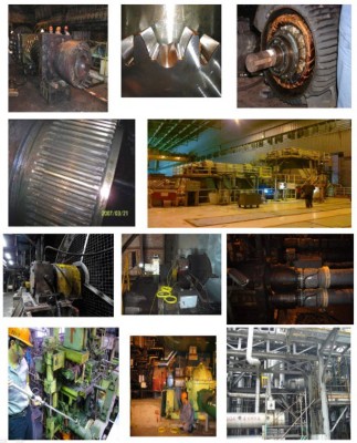
A conventional monitoring and diagnosis system uses the same or very few indicators and criteria to monitor and diagnose various machine conditions regardless of the nature of the operation of the machine (Figure 2). Therefore, these systems are prone to false alarms or missing alarms. To make it worse, with diverse monitored equipment (Figure 3), a complicated operation regime, and widespread applications in numerous process lines in an integrated steel factory, it is impractical to achieve our goals with only a few diagnosis experts. Thus, we discovered the best way to improve the effectiveness and efficiency of our MCM system was to introduce some artificial intelligence methods.
A Breakthrough in Diagnosis technology
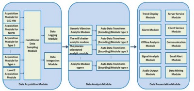
Our new online MCM system, FOMOS-AI, is a patented self-learning system that is based on equipment behavior instead of conventional methodology (Figure 4). To extract useful condition indicators from vibration signals, we categorized the operation context of the monitored equipment into four different patterns, including constant speed and stable load, constant speed and variable load, variable speed and load, and reciprocating. There are six analysis modules for data extraction (Figure 5).
To obtain better self-diagnosis accuracy, each module integrates data by acquiring several interactive condition signals simultaneously. Moreover, if a facility experiences a specific failure, the analysis module can increase system intelligence and failure identification capabilities (Figure 6). Therefore, it can take large amounts of data and automatically convert it to actionable information for the condition monitoring and prognostic technology.
System Software Design Features
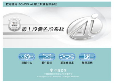
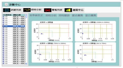
We designed both the hardware and the software architecture of FOMOS-AI with the highest flexibility in mind so various fault diagnosis and detection algorithms can be implemented. The system software programmed with LabVIEW consists of a diagnostic center, mail setting, and baseline setting (Figure 7).
Hardware can be implemented with either NI PXI or CompactDAQ, and the system features:
- Flexible implementation that can be ready for monitoring and diagnosis after picking the required analysis modules.
- Customizable diagnosis rules that accumulate and a modular software structure (Figure 8).
- Abundant signal processing and analysis functions (Figure 9).
- Virtual measurement points, meaning one physical sensor can perform various measurements through a number of virtual points.
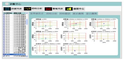
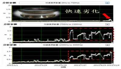
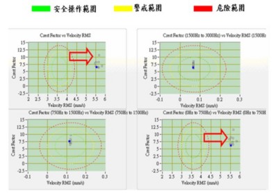
- A baseline setup in which equipment conditions can be determined by observation of the diverse changes of the vibration signals through multiple indicators. A multidimensional baseline and alarm setting are established using a statistical analysis or expert diagnosis based on operation regime and machine behavior (Figure 10 and Figure 11). Figure 12 shows an example of a failed main motor cooling fan of a high-speed machining (HSM) finish mill, which showed no signs of deterioration by overall trends but a rise of acceleration in high-frequency band in early July, and functional failure of the motor bearings was confirmed in early November.
- Automatic failure encoding and reporting in which alarm messages are reported daily to a preset mail group through the company email system.
Application
Depending on the operation regime and dynamic behavior of the equipment, FOMOS-AI adopts unique data acquisition and analysis modules with built-in specific diagnosis algorithms. The result not only has early alerting and precise diagnosis, but is also a more cost-effective maintenance process. We have experienced less shutdown and can perform more scheduled maintenance, which proves beneficial to the overall equipment effectiveness (OEE). These few examples demonstrate the true value of FOMOS-AI in our rolling mill:
1. Abrasion wear of sliding liners in the SSP
To improve productivity, we introduced an SSP to our HSM in 2004. However, while forging the steel slab, high impact and abrasion wear can lead to premature damages to the facilities. Similar SSPs have reported disastrous damages such as broken main beams, seized synchronizer bearings, and synchronous shaft fractures.
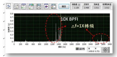
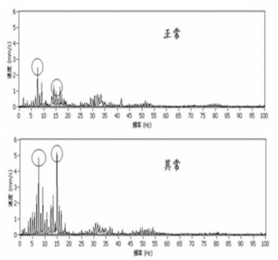
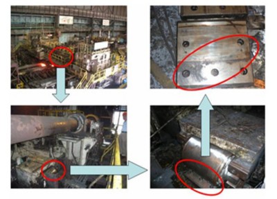
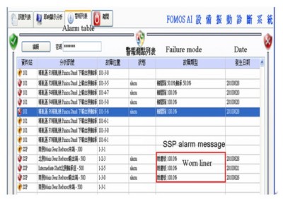
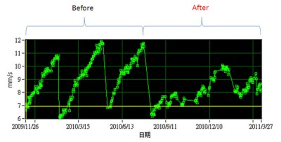
FOMOS-AI has successfully predicted several different failure modes since it was first implemented. In 2010, abrasion wear of three sliding liners was detected during the forging process (Figure 13). This failure mode was confirmed by spectrum analysis (Figure 14) and field inspection. The end users felt comfortable tracing this event and decided when to replace the parts during scheduled maintenance (Figure 15). Alternative materials of sliding liners have been tested to see if their performance is better by trending the deterioration rate through FOMOS-AI. Since new sliding liners were installed in August, 2010 (Figure 16), impact vibration was alleviated and the service life of the whole SSP was greatly improved.
2. Fretting wear of gear coupling spline between spindle and pinion stand
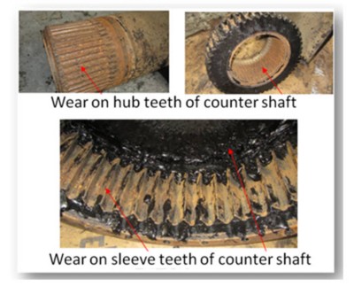
A gear coupling is designed as a connection between a pinion stand and UJ spindle of a finishing mill. An enlarged gap between splines under continuous threading impact and high transmitting torque may accelerate fretting wear (Figure 17). Excessive wear of the splines may breatk the coupling sleeve. This leads to tremendous production loss and high equipment repair costs. This failure mode was easily recognized by vibration waveform and STFT analysis from FOMOS-AI, and the lead time for the required maintenace is around two months.
Results
FOMOS-AI is a newly developed diagnosis technology dedicated to expanding insufficient knowledge of various facilities regardless of conventional vibration criteria. Unknown failure modes can be triggered, and trending can be confirmed through intelligent analysis modules, self-learning algorithms, and automatic encoding. By using the NI platform, we could easily and effectively customize FOMOS-AI to detect unclear failure modes without consulting experienced vibration experts.
FOMOS-AI can prove itself in the visualization of potential failures on critical equipment because of the versatile applications we can use it on at CSC (Figure 18). It helped us save around 350 million TWD and also helped us win excellence awards from the World Steel Association because of our high OEE and outstanding practice of predictive maintenance.
Author Information:
Dr. Zhizhong Wang
China Steel Corporation Iron and Steel R&D Department
Taiwan
Kenny.expert@xwin.com.tw
Products in this Case Study

