Measuring Load Transient Regulation with the LDO Measurement Suite in InstrumentStudio
Overview
High-performance power supplies are crucial to the operation of circuits where voltages must be reliable. The low dropout regulator (LDO) is one example of this type of power supply. An LDO’s ability to regulate load transients is a critical specification to measure its performance.
First, this document outlines the challenges of measuring load transient regulation, due to the need for high-speed current pulses that test equipment struggles to meet. Then, it details the steps taken to design a circuit to solve those challenges, and to measure load regulation in NI InstrumentStudio with the help of the Soliton LDO Measurement Suite Add-on.
Contents
- Challenges with Load/Line Transient Measurements
- Load Transient Reference Circuit
- LDO Measurement Suite Example
- Additional Resources
Challenges with Load/Line Transient Measurements
Modern LDO’s have load transient regulation specifications for voltage droop max for a given current pulse at a given slew rate. This can cause challenges for test setup for this specification, given the high-speed current pulses that modern LDOs specify against. Finding test equipment to meet this challenge can be difficult.
Off-the-shelf power supplies or even precision SMUs have limitations to their ability to create a controlled slew rate current pulse. When off-the-shelf equipment that can meet these current pulse specifications is not available, turning to a custom circuit may be an option.
Described in the following section is an example circuit that can improve upon the capabilities of most power supplies and meet many of these challenging load current transient specifications.
Load Transient Reference Circuit
This reference circuit primarily comprises an op amp, a power MOSFET, and a linear regulator. An NI arbitrary waveform generator provides a pulse to control the flow of current through the MOSFET. This allows for the creation of a fast-changing pulse load. Using different arbitrary waveforms allows the customization of pulse loads with varying amplitudes, duration, and rise/fall times.
Test setup block diagram for using reference circuit with Soliton LDO suite
Schematic of Load Transient Reference Circuit
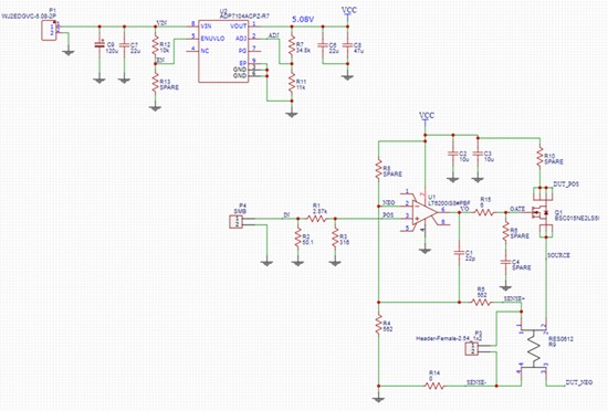
The op amp in this circuit, U1, is a high-speed op amp used to control the gate voltage of the MOSFET responsible for regulating the load current of the LDO. It is important that the op amp has a high bandwidth (165MHz in our case) to provide fast load current slew rates, as well as a high output current (60mA in our case) to drive the MOSFET capacitance. A linear regulator provides a fast, stable power source to the op amp Vcc, and the (optional) circuit comprising R5, R4, and C1 provides stability to keep the op amp output from oscillating.
The MOSFET controls the load current based on the gate voltage supplied from the output of the op amp. The MOSFET is a power-MOSFET operating in linear mode, meaning that it is operating in its saturation region as shown in the graph below:
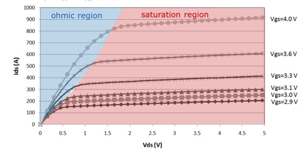
In this region, Ids is completely a function of the gate voltage Vds, and a linear change in Vgs will produce a predictable linear change in Ids. In this way, the slew rate of the load current can be completely controlled by the output of the op amp, which itself is controlled by the output of the waveform generator.
The 4-terminal resistor R9 is used as a current sense resistor. The value for this resistor can be tuned to balance between power dissipation and voltage signal fed back to the op amp. A larger resistance value will increase Vsense and maximize the signal-to-noise ratio, while a smaller resistance value will minimize power dissipation and self-heating. The power dissipation can also be controlled by tuning the duty cycle of load transient current pulses. This will minimize the average current through the MOSFET and current sense resistor.
The resistor R10 is an optional resistor to allow bias current to flow through the MOSFET. This will keep it biased ON to allow the MOSFET to respond more quickly to a current pulse without adding load current to the DUT itself. This is for the case where a load pulse for the transient test starts from 0A, which normally introduces a delay on the order of 100ns for the op-amp to turn on the transistor and respond to the pulse. By adding R10 and setting it to bias at 5-10mA, the transistor will be kept on and will respond immediately.
Component | Manufacturer | Model |
|---|---|---|
Linear Regulator | Analog Devices | ADP7104ACPZ-R7 |
Operational Amplifier | Linear Technology | LT6200IS8-#PBF |
MOSFET | Infineon | BSC015NE2LS5I |
Board layout of circuit
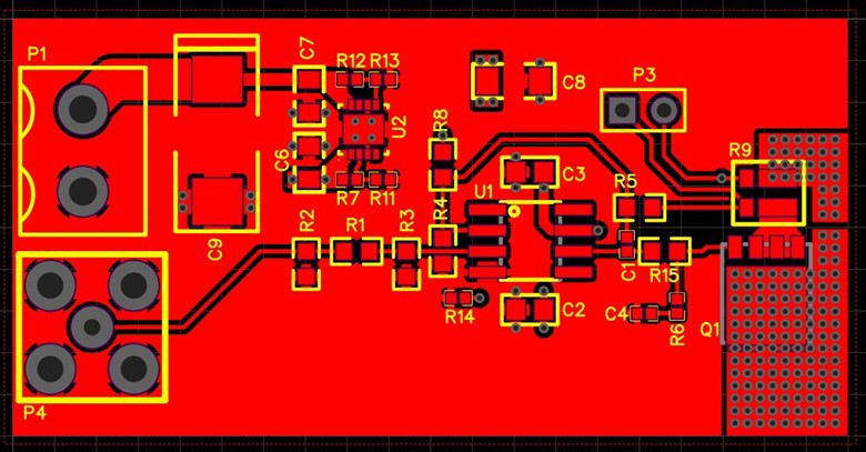
For the PCB design, it’s important to follow guidelines for high-speed circuits. Some suggestions and details for designing a board layout are given below:
- For the arbitrary waveform input, connector P4 is an SMB style coaxial connector.
- Use ground planes on top and bottom of the PCB for high-speed signal integrity.
- Use short, direct traces and avoid vias to minimize inductance.
- Keep critical components (C1-C3, R4) close to the high-speed op-amp (U1) for stability of the circuit.
- Q1 and R9 are attached to a large copper area with many vias on top to a plane on bottom layer for heat dissipation.
- If this will be incorporated into a DUT board, it is best to keep Q1 and R9 very close to the DUT output to minimize inductance for the high slew rates desired.
- If this board will be separate from the DUT board, it’s critical to use a short pair of heavy gauge twisted wires for low inductance.
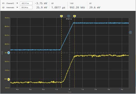
Below are a couple of examples of pulse loads that can be created with this circuit. The blue trace shows the AWG’s output voltage, while the yellow shows the voltage across a 20mOhm shunt resistor (load current from LDO).
~1.5A/us slew rate:
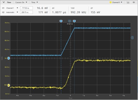
By creating an arbitrary waveform which steps the output voltage ~150mV over 1us, we were able to step the load current ~1.5A/1us.
~0.5A/1us slew rate:
Circuit limitations
In addition to the circuit component power limitations, this circuit has the following performance limitations:
- The accuracy of the current pulse will be limited by the accuracy specification of the op-amp and sense resistor chosen. Refer to the manufacturer’s data sheet of these devices to determine the error sources in the current pulse.
- The self-heating of the shunt resistor. Again, refer to the manufacturer’s data sheet for the part chosen. Consider the initial accuracy specification of the resistor as well as the temperature coefficient (TC) of the resistor in your calculations.
- The slew rate of the current pulse will be limited by the bandwidth of the op-amp chosen, as well as the overall bandwidth of the circuit. For this example circuit, a slew rate of approximately 1A/us is achievable. It is possible to improve the circuit example by choosing a higher bandwidth op-amp. For this change, the stability design of the circuit will also need to be modified.
- The amplitude and the average current of the current pulse will be limited by the peak and average power capabilities of the transistor and the sense resistor. Good thermal management will insure proper performance of the circuit.
- Maximum load voltage will be limited by the maximum drain-source voltage (Vds) of the transistor.
For any additional test circuit details or information, please reach out to NI support.
LDO Measurement Suite Example
The Soliton LDO Measurement Suite contains pre-built measurements for line/load regulation, line/load transient, power supply rejection ratio (PSRR), and dropout voltage, with options for implementing additional measurements through Soliton engineering engagement. The intuitive InstrumentStudio panel allows for interactive operations and debugging, as well as the ability to export measurement and instrument configurations for a simplified path to automation. Below we’ll demonstrate how to use the panel to configure and perform a load transient test using the load transient reference circuit.
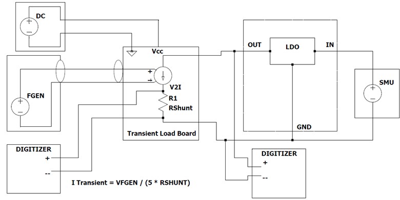
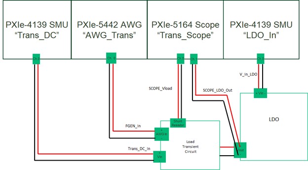
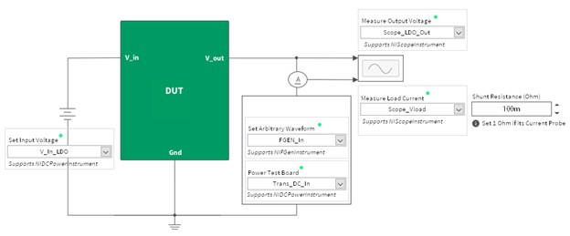
- Connect the instruments as shown in the following diagram. Note that you may use different models of NI instruments based on specific needs or availability. The NI MAX aliases for the instruments used in this example are shown in quotations in the diagram.
Connections for Load Transient Test using Solution LDO Measurement Suite
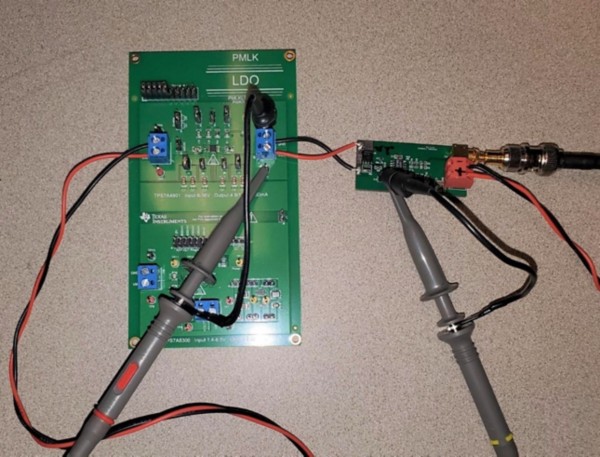
Physical connections in test
- Using the circuit with the Soliton LDO Measurement Suite:
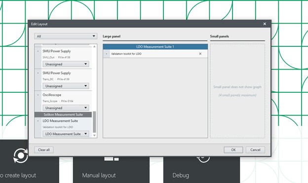
Open InstrumentStudio and create a layout with the Soliton Measurement Suite Panel. Place any side panels you’d like for debugging or on the fly configuration. For example, you can create a small panel for the SMU connected to the input of the LDO so that you can increase the current limit beyond the default 100 mA.
Save the project.
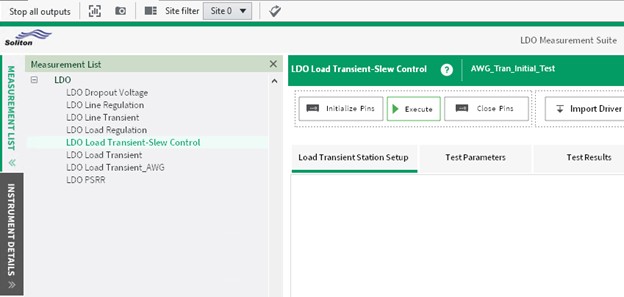
- In the Measurement List tab, select the LDO Load Transient-Slew Control measurement.
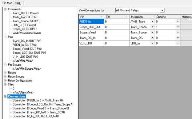
- In the Instrument Details tab, click on Manage Instruments and define your pinmap file based on the instrument connections used in your setup. The pinmap configuration pictured below matches the connection diagram shown above.
- Use the dropdowns in the diagram to select the corresponding pins as defined in the pinmap. Set the shunt resistance to match the value on the load transient circuit (100mΩ in this example).
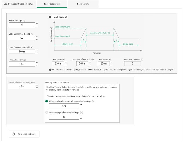
- Click the Test Parameters tab and specify the parameters for the pulsed load waveform you’d like to use, the input and output voltage for the LDO, and how to calculate settling time.
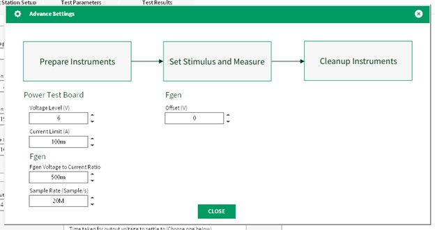
- Click Advanced Settings to set the power parameters for the Load Transient Circuit, the AWG voltage to current ratio (in this case 1:2 or 500m), AWG sample rate, and an offset for the AWG. You can use this offset to provide a bias to the transistor.
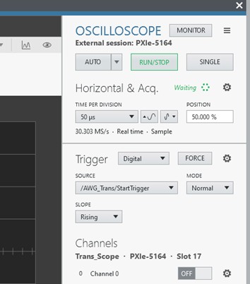
- After configuring the Test Parameters, open a panel for the oscilloscope in the system (or refer to the panel you included in the initial InstrumentStudio setup) to configure it to properly trigger and capture the waveform.
Scope Settings:- Sampling rate in Horizontal setting
a. Set this value such that the transient response waveform is captured. - Set the Voltage Range of CH0
a. AC – Coupling – Voltage Range to capture the transient response of the LDO (recommended)
b. DC – Coupling – Voltage Range to capture the voltage level of the LDO output voltage - Trigger Settings
a. Digital Trigger from Fgen (Recommended)
i. Select the Start trigger from a Scope panel:
b. Edge Trigger from CH1 – Set the trigger voltage level such that the scope will get the trigger when executing the Load current sequence configured. Note: Proper trigger threshold should be set to capture transient response.
- Set the Voltage Range of CH1 such that it can capture the Load Current steps
*All other instrument settings can be controlled/modified using soft front panels. These settings can also be retained by importing them to the plugin. Please refer User Manual for more information on importing driver configurations.
- Sampling rate in Horizontal setting
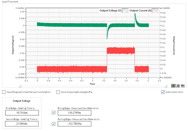
- Click Execute to run the test as configured. The Test Results tab then shows the results from the test.
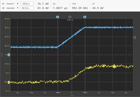
Overall test result:
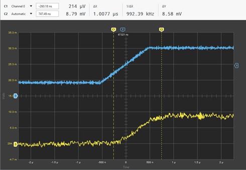
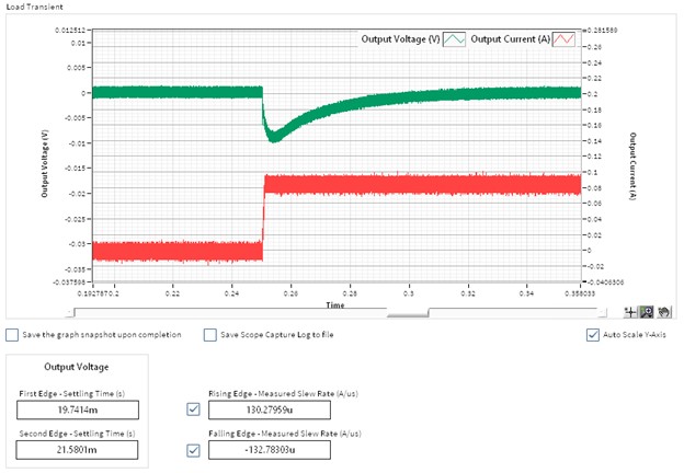
Focusing on first transition:
You can save specific test configurations for reuse. To do this, first click Import Driver Configuration to load the current driver configurations into LDO Suite memory—the LDO Suite configuration will now include the instrument driver configurations. Then click Save in the upper right corner of the LDO Measurement Suite panel. You can reload configurations in the panel later or use the saved configurations in automated measurements using the API. You can also save the results to a .csv file by clicking Open Datalog.
Additional Resources
To access the Soliton Measurement Suite User Manual, open the LDO Measurement Suite and click the green question mark icon in the top-right corner of the window.
To access the Soliton Load Slew Control Measurement Manual, open the LDO Measurement Suite, go to Measurements List >> LDO Load Transient-Slew Control, and click the green question mark icon in the top-left corner of the LDO Load Transient Control window.
- External Link: Infineon BSC015NE2LS5I Specifications
- External Link: Linear Technology L6200/LT6200-5/LT6200-10/LT6201 Data Sheet
- External Link: Analog Devices ADP7104 Specifications
- External Link: Linear Technology: Load Transient Response Testing for Voltage Regulators
For more information on the Soliton LDO Measurement suite please visit the product page.