Using Duplicate Count Prevention for Counter Tasks in NI-DAQmx
Contents
- Overview
- Counter Application without Duplicate Counting
- Counter Application with Duplicate Counting
- Duplicate Count Prevention
- Enabling Duplicate Count Prevention in NI-DAQmx

Overview
Counter applications sometimes require a buffered acquisition where the buffer is configured to perform counter measurements for a specified period of time before latching the counter register value. In buffered counter measurements, the unknown signal is connected to the gate input of the counter and a signal with a known frequency is connected to the source input of the counter. These signals are used to determine the period or frequency of the unknown signal. The source input (signal with known frequency) is usually one of the device's internal timebases.
However, when using an external source input as a reference for determining the period or frequency of an unknown signal, there is a possibility of getting an incorrect measurement or counts due to having a complete gate period without an active source edge. This situation is referred to as duplicate counting.
Counter Application without Duplicate Counting
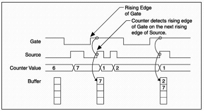
Consider a buffered period measurement with an external source input of known frequency and a gate input with unknown frequency as shown in Figure 1.
Figure 1. Accurate Source Edge Counting.
On the first rising edge of the Gate, the current count of 7 is stored. On the next rising edge of the Gate, the counter stores a 2 since two Source pulses occurred after the previous rising edge of Gate.
The counter samples the Gate signal with the Source signal. So the counter does not detect a rising edge in the Gate until the next Source pulse. The counter also stores the values in the buffer on the first rising Source edge after the rising edge of Gate.
Counter Application with Duplicate Counting
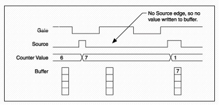
Consider another buffered period measurement with a slow or non-periodic external source input as shown in Figure 2. Notice that there is a gate period with no active edge on the external source input occurring after the first rising edge of Gate. This causes the counter register to latch the current register count onto the memory on the next rising edge of the gate. The result is an erroneous measurement that returns the previous count register value of (7) instead of zero.
Figure 2. Duplicate Count.
Duplicate Count Prevention
Duplicate count prevention, also known as synchronous counting mode, ensures that a counter returns correct data in applications that use a slow or non-periodic external source. Duplicate count prevention applies only to buffered counter applications such as measuring frequency or period. In such buffered applications, the counter should store the number of times an external source pulses between rising edges on the Gate signal.
With duplicate count prevention enabled, the counter synchronizes both the Source and Gate signals to the maximum (80 MHz) internal timebase. By synchronizing to the timebase, the counter detects edges on the Gate even if the Source does not pulse. This enables the correct current count to be stored in the buffer.
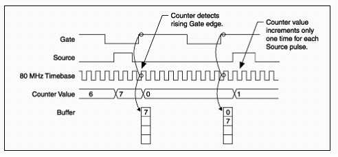
Consider Figure 3 with duplicate counting prevention. Normally, the counter value changes synchronously to the Source signal. With duplicate count prevention, the counter value changes synchronously to the maximum internal timebase. Thus the internal timebase is really the source.
Figure 3. Duplicate Count Prevention.
Furthermore, only the first edge of the counter’s timebase is used to increment the count register once each external source edge is detected even if the Source pulse is long. All the other timebase edges that occur while the external source input is high are ignored. If no source edges are detected between two gate edges, as shown in Figure 3, duplicate count prevention ensures that pulse measurements return zero because the external source must be logic high to allow the internal timebase to increment the count register. This reduces your maximum source frequency to quarter of the original maximum (80MHz) timebase for NI-STC II and NI-TIO boards. Therefore duplicate count prevention should only be used if the frequency of the Source signal is 20 MHz or less.
Duplicate count prevention should only be use in the following situations:
- Counter measurements
- The counter Source is using an external signal (such as PFI x)
- The frequency of the external source is 20 MHz or less
Enabling Duplicate Count Prevention in NI-DAQmx
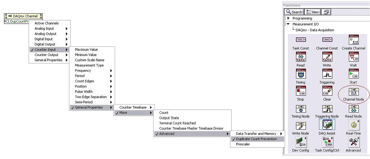
To enable duplicate count prevention in NI-DAQmx, you can set the channel property node to Enable Duplicate Count Prevention. It is important to note that M Series devices enable duplicate count prevention by default when you are performing a counter measurement that may require it. If you wish to specify this property (or check whether or not it is enabled), you can place a DAQmx Channel Property Node and select Counter Input->General Properties->More->Advanced->Duplicate Count Prevention as shown in Figure 4.
Figure 4. Duplicate Count Prevention Property Node.
Figure 5 shows a sample counter application that performs buffered counter measurement with Duplicate Count Prevention enabled. The complete application program is attached below
Figure 5. Duplicate Count Prevention.


