Time-based Synchronization of Analog Input C Series Modules with NI-DAQmx in LabVIEW
Overview
CompactDAQ controllers and chassis offer support for a wide variety of C Series I/O modules with diverse measurement types such as acceleration, temperature, and strain. When applications require tight synchronization between measurements, the CompactDAQ hardware in conjunction with the NI-DAQmx API allow user's flexible configuration options to achieve the desired time correlation across multiple C Series I/O modules. This document highlights time-based options available to achieve synchronization between C Series I/O modules.
Contents
- C Series Analog Input Modules
- Time-Based Synchronization Vs. Signal-Based Synchronization
- Multichassis Synchronization
- Multi-Rate Synchronization
- Multichassis, Multi-Rate Synchronization with Mixed Modules (NI-DAQmx 19.5 and later)
- Multichassis, Multi-Rate Synchronization with Mixed Modules (DAQmx 18.6 to DAQmx 19.5)
- Multichassis, Multi-Rate Synchronization with DSA Modules (DAQmx 18.6 and earlier)
- Conclusion
- Additional Resources
C Series Analog Input Modules
C Series Analog Input Modules can be categorized into four groups based on their synchronization: Reference Clocked, Delta Sigma, Slow Sampled, and Successive Approximation Register (SAR). Reference Clocked modules convert using an internal onboard clock. This onboard clock is disciplined using a phase lock loop to another internal clock or can be disciplined to clocks external to the module. Delta Sigma Modules use a 24-bit ADC and convert using a clock internal to the module. Slow Sampled Modules use a 24-bit ADC and convert using an external clock that originates from the CompactDAQ controller or chassis. Lastly, SAR Modules use a Successive Approximation ADC (12- or 16-bit) and convert using an external clock. The method of implementing synchronization may depend on the group that the module falls into. A list of module groupings can be found in the Resources section of this tutorial. In this tutorial, synchronization is defined as the steps or techniques used directly or indirectly via the DAQmx driver to start measurements at the same time and to remove drift between subsequent measurements. While the result of these steps increases the sample to sample alignment, the focus is to prevent drift.
Time-Based Synchronization Vs. Signal-Based Synchronization
Time-based synchronization and signal-based synchronization are two distinct synchronization paradigms you can use to synchronize measurements with C Series modules. This document discusses time-based synchronization. For details regarding signal-based synchronization, please view Signal-based Synchronization of Analog Input C Series Modules with NI-DAQmx in LabVIEW.
- Signal-based synchronization describes synchronization via signals routed between devices. A device that waits on a digital high to occur on a trigger line is using signal-based synchronization.
- Time-based synchronization describes synchronization via events scheduled with respect to the time on a device. A device that waits on the local time to reach 5:00 PM to start is using time-based synchronization.
Each method of synchronization has its advantages, and the right synchronization method varies by application.
Multichassis Synchronization
The cDAQ-9185, cDAQ-9189, cRIO-904x and cRIO-905x models offer three distinct clocks (10 MHz, 12.8 MHz, and 13.1 MHz) to Delta Sigma and Reference Clocked Modules. When using Delta Sigma or Reference Clocked Modules in these chassis DAQmx will default to using the chassis clocks to acquire or generate signals instead of the clocks onboard the modules.
When the time-aware chassis share the same grand master, all clocks onboard the chassis are synchronized to this grand master. Thus, clocks across multiple chassis are synchronized to each other. This process is done automatically and without user input. Since each module in the chassis will default to using the chassis backplane clocks for generation or acquisition, clocks used by each module (master timebase, sample clock, and/or reference clock) will all be synchronized. To synchronize the module acquisitions or generations between chassis, ensure that the Start Trigger is sent at the same moment.
Having multiple devices in the same task will compensate for timing difference between modules automatically, which greatly simplifies task setup and makes this configuration ideal for small to moderately sized acquisitions. There are a few caveats:
- Having a large number of channels in the same task will cause task set up to take longer as all channels are configured to start at the same time. This extra set up time must be accounted for when setting a time start trigger or error -209840 may occur.
- Having multiple chassis in the same task will make the task less reliable, as losing contact with any chassis in the task will stop the task. For a more robust configuration, use one task for each chassis.

Figure 1: Multichassis Synchronization with the cDAQ-9185 or cDAQ-9189
Multi-Rate Synchronization
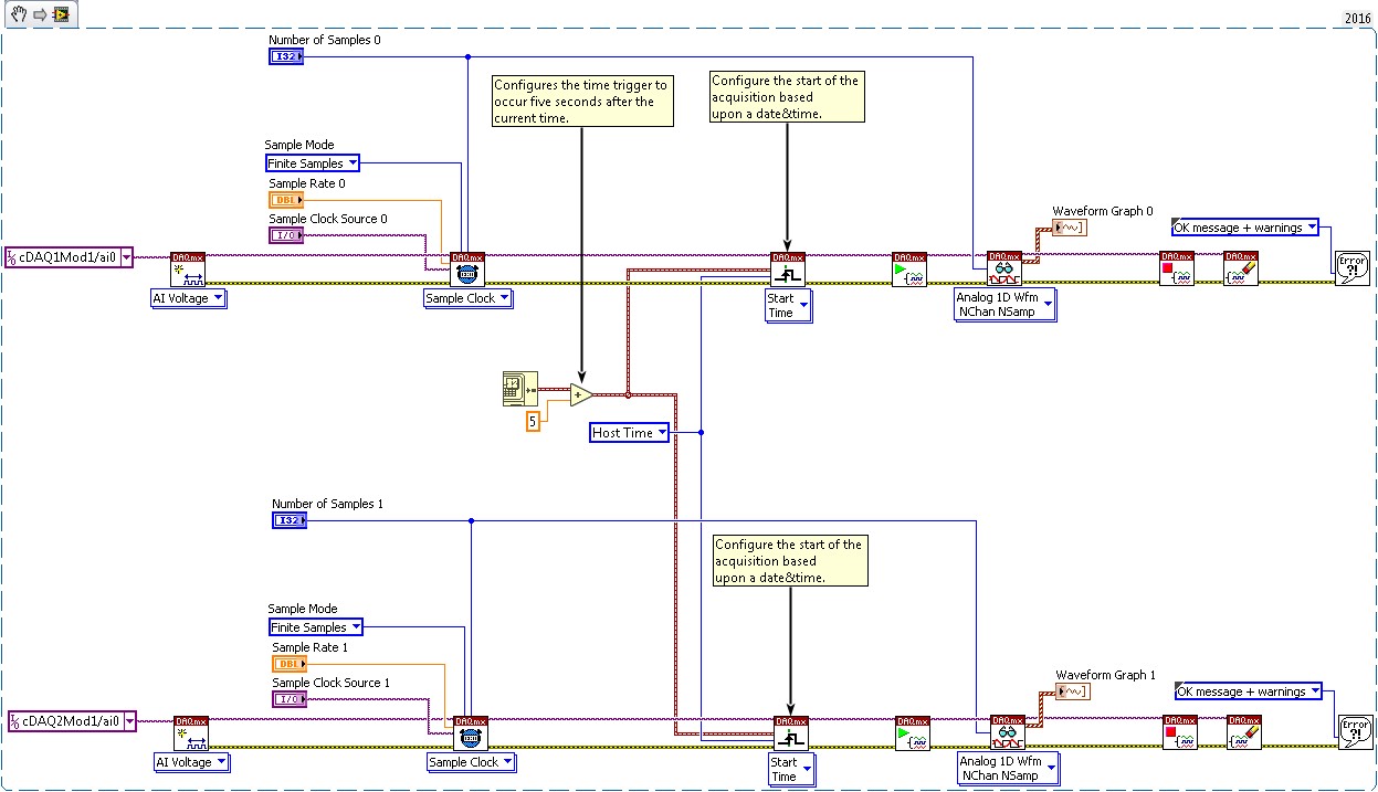
Placing all the modules from various chassis in one task to achieve synchronization is not a feasible solution for certain modules and locks all the modules to a single sample rate. To synchronize modules in these cases, use separate tasks, configure a start trigger for each task, and set the start trigger to begin at the same time. A shared start time trigger will not compensate for differences in front-end architectures, so an offset may be present in data acquired this way. Compensation techniques are discussed in the examples following this one.
Figure 2: Multichassis and Multirate Synchronization with the cDAQ-9185 or cDAQ-9189
Multichassis, Multi-Rate Synchronization with Mixed Modules (NI-DAQmx 19.5 and later)
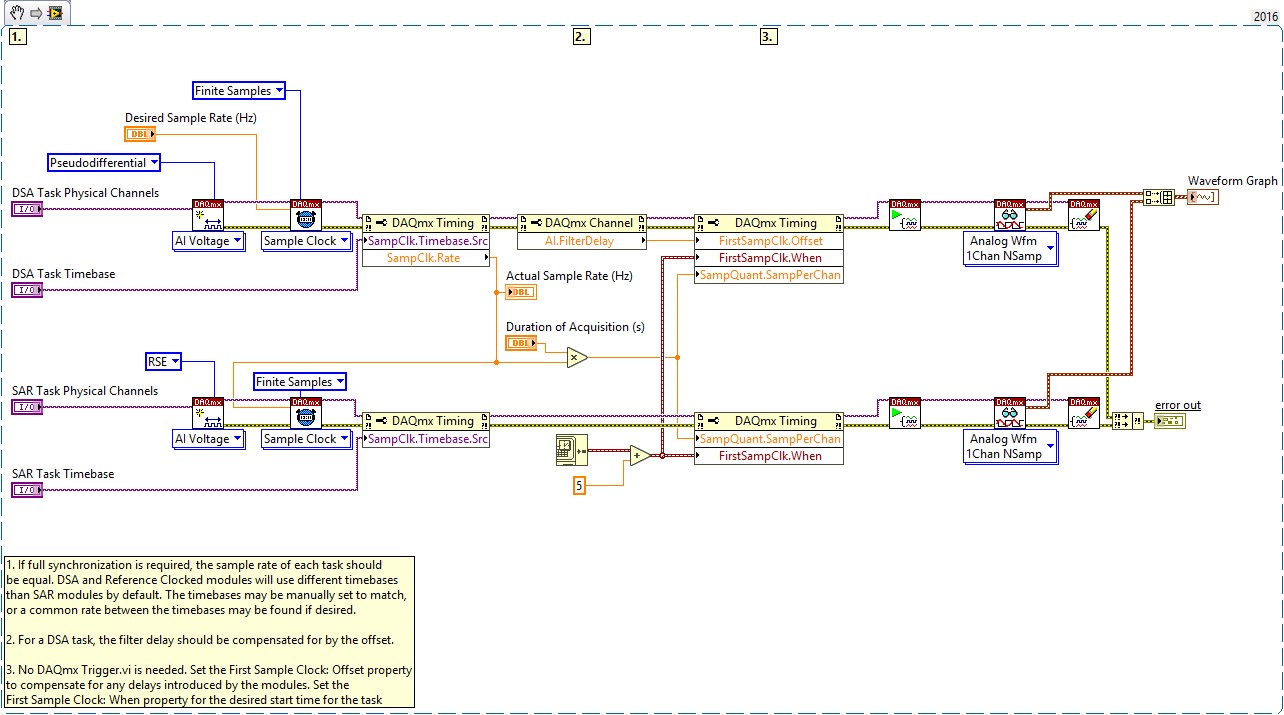
NI-DAQmx 19.5 introduces the First Sample Clock Time: Offset property, which greatly simplifies the synchronization of multiple modules with different sample rates or with different front-end architecture. This property allows you to compensate for filter delay or other factors by offsetting the first sample clock time of a task by a specified amount. Using this property avoids the need to use complex methods like those described in the following sections for older versions of NI-DAQmx.
To better understand this property, consider the case in which two tasks with different front-end architecture require synchronization. One task contains a DSA module, and the other contains a SAR module. The SAR module will have samples available immediately when the task starts, but the DSA module will have filter delay between the time the task starts and the time when the first sample is available. By simply running these tasks side by side with the same start time and rate, you would notice a time offset between the data from each task.
By setting the First Sample Clock Time: Offset property to the filter delay of the DSA module, the time of the first sample clock pulse is shifted by the filter delay time. This compensates for the filter delay in-line with the rest of the task setup, which allows the DSA module to have filtered data available at the same time the SAR module samples and eliminates the effect of filter delay from the measurement. Refer to the example code below for an example of how to use this property.
Figure 3. Multichassis Synchronization Using First Sample Clock: Offset property
Multichassis, Multi-Rate Synchronization with Mixed Modules (DAQmx 18.6 to DAQmx 19.5)
Delta Sigma and Reference Clocked Modules will default to the available onboard (13.1 MHz, 12.8 MHz, and 10 MHz) chassis clocks when in time-aware chassis. Therefore, when attempting to perform a multirate synchronization in a single cDAQ-9185 or cDAQ-9189, you only need to share a Start Trigger and/or synchronization pulse to synchronize the two tasks. The Sample Clocks, Master Timebase, and Reference Clocks originate from the chassis and are synchronized, thus measurements using these clocks will be synchronized.
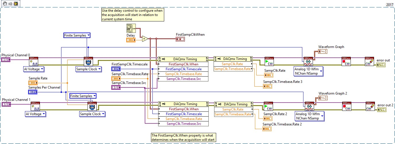
Starting in DAQmx 18.6 a new DAQmx Timing Property is available called First Sample Clock When. This property allows you to set the time when the first sample clock will be generated in terms of System Time or I/O Device Time. This property performs the calculations demonstrated in Figure 19 internally, including start trigger time, difference in reset times, and first sample alignment when using multiple rates. The First Sample Clock When property can be used to align acquisition start times on any combination of module types including DSA, SAR, Slow Sampled and FieldDAQ devices. The example below demonstrates how to use the property.
Figure 4. Multichassis Synchronization Using First Sample Clock: When property
Multichassis, Multi-Rate Synchronization with DSA Modules (DAQmx 18.6 and earlier)
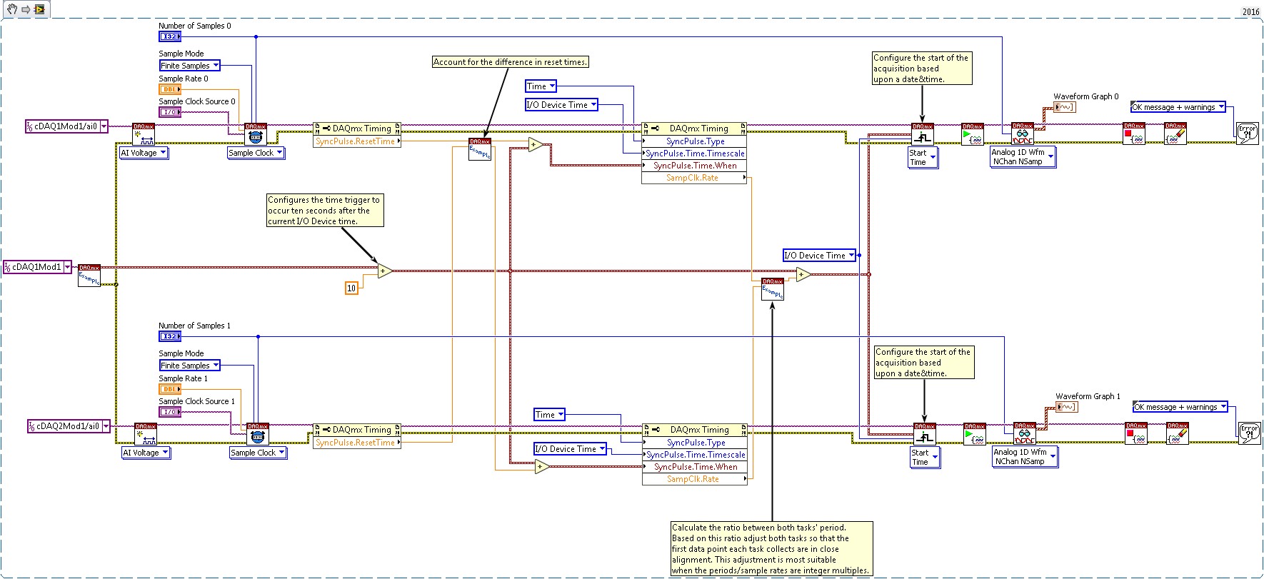
When Delta Sigma and/or Reference Clocked Modules are running at different rates, we must account for the difference in reset times and the variable number of samples that occur due to the difference in sample rates. The difference in reset times are accounted for by sending the synchronization pulse x seconds before the start trigger, where x is equal to the longer reset time. The variable number of samples is accounted for by analyzing the ratio between the two acquisition periods and adjusting the synchronization pulse based on this analysis. The subvis necessary for this example are attached to this document in the top right hand corner.
Figure 5: Multichassis and Mutlirate Synchronization with the cDAQ-9185 or cDAQ-9189 for Delta Sigma and Reference Clocked Modules
I/O Device time is used in the above example due to the accuracy in translation between Host Time and I/O Device time.
Conclusion
This tutorial has demonstrated several time-based synchronization options. Initially, all channels were in the same task, so all channels were locked to the same start time and sample rate. You can improve the synchronization flexibility by splitting the task between modules with different requirements. If the modules you use require different sample rates, you must make special considerations depending on the type of module you are using. The options outlined above represent several different ways to synchronize C Series modules within the timing requirements of many applications.
Additional Resources
C Series Modules:
- Delta Sigma Modules: 9202, 9218, 9225, 9227, 9228, 9229, 9230, 9232, 9234, 9235, 9236, 9237, 9238, 9239, 9242, 9244, 9246, 9247, 9250, 9251
- Slow Sampled Modules: 9207, 9208, 9209, 9210, 9211, 9212, 9213, 9214, 9216, 9217, 9219, 9224, 9226
- SAR Modules: 9201, 9203, 9205, 9206, 9215, 9220, 9221, 9222, 9223
- Reference Clocked Module: 9775
- Chassis Synchronization Module: 9469
- Time Aware CompactDAQ Chassis: cDAQ-9185 and cDAQ-9189
- Configuring the NI 9469 in Measurement & Automation Explorer
- Programmatically Configuring the NI 9469 in LabVIEW
- Learn 10 Functions in NI-DAQmx and Handle 80 Percent of Your Data Acquisition Applications
- NI-DAQmx-Based TSN Synchronization Accuracy Explained
- How to Achieve High-Accuracy Measurements With NI-DAQmx-Based TSN Devices
- Designing Distributed TSN Ethernet-Based Measurement Systems
- NI CompactDAQ Advisor
- Signal-based Synchronization of Analog Input C Series Modules with NI-DAQmx in LabVIEW


