NI-DAQmx Hardware-Timed Single Point Lateness Checking
Overview
NI-DAQmx supports hardware-timed single point sample mode in which samples are acquired or generated continuously using hardware timing and no buffer. Hardware-timed single point mode is commonly used on LabVIEW Real-Time platforms for control applications which require input and/or output within a deterministic period of time. In order to check if the software operations are keeping up with the hardware timing, it is necessary to do lateness checking. Changes introduced in NI-DAQmx 7.4 provide increased flexibility when performing hardware-timed single-point operations on real-time platforms. In NI-DAQmx 7.4 and later there are three options for lateness checking:
1) Strict Lateness Checking (Wait For Next Sample Clock)
2) FIFO Overflow Lateness Checking (Report Missed Samples)
3) No Lateness Checking
This tutorial briefly explains the three lateness checking modes and contains sample applications that demonstrate new functionality in NI-DAQmx 7.4. The applications are based on requirements common to real-time applications using single-point NI-DAQmx tasks. These samples are drawn from a basic set of example implementations meant to aid in the design of more complex applications. The examples pertain to control applications but are applicable to other single-point applications such as hardware-in-the-loop, event response tasks, and in-line signal manipulation.
Each application case contains a proposed solution that describes the use of the new features in NI-DAQmx 7.4, as well as a specific application example, a timing diagram, and a LabVIEW block diagram. Each application case also contains notes with advanced information to clarify implementation details, optimizations, and error conditions.
Contents
- Strict Lateness Checking (Wait For Next Sample Clock)
- FIFO Overflow Lateness Checking (Report Missed Samples)
- No Lateness Checking
- Application Case 1 - Hardware-Timed Simultaneously Updated I/O
- Application Case 2 - Hardware-Timed Simultaneously Updated I/O with Data Exchanges between Time-Critical and Non-Time-Critical Loops
- Application Case 3 - Hardware-Timed Input, Software-Timed Output
- Application Case 4 - Hardware-Timed Counter Tasks
- Application Case 5 - Software-Timed I/O
- Application Case 6 - Hardware-Timed Simultaneously Updated I/O Using the Timed Loop
- Learn More
Strict Lateness Checking (Wait For Next Sample Clock)
Among the new features introduced in NI-DAQmx 7.4 is the Wait For Next Sample Clock VI, which guarantees tight synchronization between the hardware layer and the software layers when performing hardware-timed single-point tasks. This VI provides an accurate way to correlate block diagram execution to hardware signals, such as the sample clock for the given task, while at the same time providing feedback on the overall real-time execution of the control loop.

'DAQmx Wait For Next Sample Clock.vi' waits until the next pulse of the Sample Clock occurs for the task to which it is wired. If an extra Sample Clock pulse occurs between calls to this VI, the second call returns an error or warning and waits for the next Sample Clock pulse. By placing calling this VI after other DAQmx functions you can guarantee that all of the functions completed prior to the next sample clock of the task wired to 'DAQmx Wait For Next Sample Clock.vi'. For more information on this VI, see the NI-DAQmx Help.
Note: The increased flexibility provided in NI-DAQmx 7.4 and later required changing behavior of the 'DAQmx Is Read or Write Late.vi' which was used in NI-DAQmx 7.3. In NI-DAQmx 7.4 the 'DAQmx Is Read or Write Late.vi' no longer performs any lateness checking. Applications using 'DAQmx Is Read or Write Late.vi' will continue to run, but this VI will not report lateness errors or warnings. It is recommended that the application be updated to use the 'DAQmx Wait for Next Sample Clock.vi' or another alternative described in this tutorial.
FIFO Overflow Lateness Checking (Report Missed Samples)
An alternative to doing strict lateness checking is to use the 'Report Missed Samples' property of the DAQmx Real-Time Property Node. Setting this property to TRUE for hardware-timed single point analog input will cause the DAQmx Read to check to where there was more than one sample available in the FIFO. If there is more that one sample is available in the FIFO, the DAQmx Read will return an error indicating that the software was not able to keep up with the hardware rate. This form of lateness checking only checks the analog input operation lateness and does not check to verify when other DAQmx operations completed with relationship to the analog input task.
Note: The 'Report Missed Samples' property is only supported for analog inputhardware-timed single point tasks. This property should not be used in conjunction with the 'DAQmx Wait For Next Sample Clock.vi' as only one form of lateness checking should be used.
No Lateness Checking
A third alternative is to perform no lateness checking by not using the 'DAQmx Wait For Next Sample Clock.vi' or the 'Report Missed Samples' property. In this mode, NI-DAQmx does no lateness checking and no errors or warnings will be reported by DAQmx functions indicating if the software is not able to keep up with the hardware rate. For advanced users, this allows for optimized performance but would require external hardware to verify the system is keeping up with the hardware rates.
Application Case 1 - Hardware-Timed Simultaneously Updated I/O
Requirement
"My I/O must be hardware-timed. All output values need to simultaneously update at the arrival of the sample clock edge."
Solution
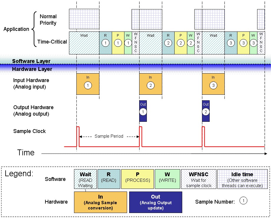
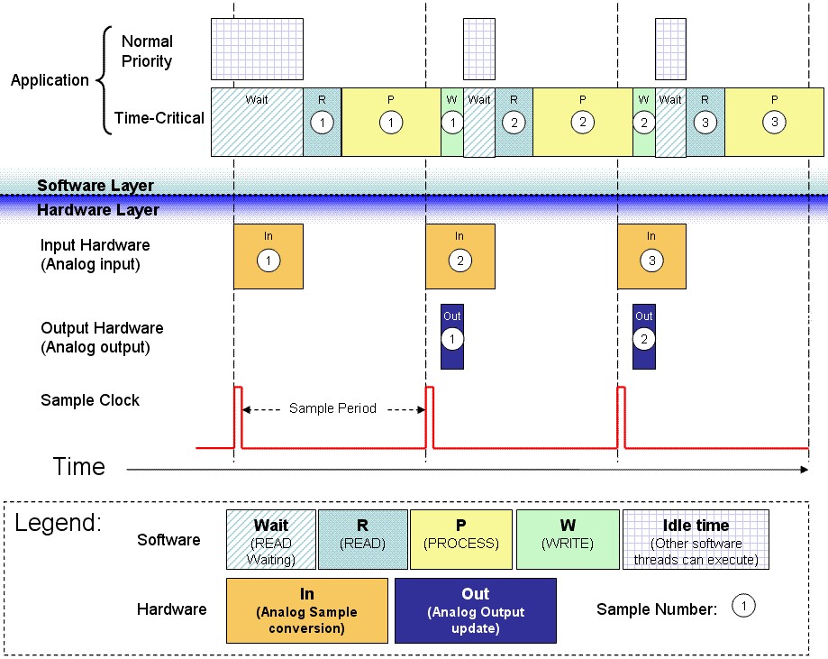
Use the Wait For Next Sample Clock VI (WFNSC) to verify that a new sample clock edge has not yet occurred.
Advantages
- The current iteration's output samples are guaranteed to be aligned with the next iteration's input samples.
- NI-DAQmx returns an error if the Wait For Next Sample Clock VI does not start before the next sample clock edge occurs.
- I/O jitter is confined to the jitter of the hardware clock, which is on the order of a few nanoseconds.
Restrictions
Read, process, and write operations are confined to the time available between the moment the device starts acquiring data and the moment the next sample clock edge arrives.
Sample Application
An example of this kind of application is an analog control loop that reads samples from a specific number of analog input channels, processes the data using a control algorithm (such as PID), and writes new control values to the analog output channels.
Sample Implementation
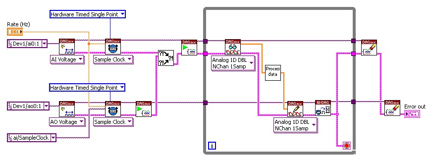
- Wire the Wait For Next Sample Clock VI to one of the hardware-timed tasks. Use dataflow wiring to guarantee that the Wait For Next Sample Clock VI executes after the AO Write call.
- If the Wait For Next Sample Clock VI does not start before the arrival of the next sample clock edge, it returns an error.
Sample Block Diagram
Notes
- Use only one Wait For Next Sample Clock VI within a LabVIEW loop. If you have multiple hardware-timed single-point I/O tasks within the same LabVIEW loop, you can connect the Wait For Next Sample Clock VI to any one hardware-timed single point task within that loop.
- If, when a cycle overflow occurs, you want to receive a warning rather than an error, set the DAQmx Real-Time»Convert Late Errors to Warnings property to True.
- Wait For Next Sample Clock has two modes of operation: Polling and Wait For Interrupt. Wait For Interrupt mode, which is the default, allows lower priority processes to execute while the time-critical loop waits for the next sample clock. Polling mode allows for higher sampling rates, but it prevents lower priority processes in the system from executing while the time-critical loop waits for the next sample clock.
- Analog DAQmx Read calls have two modes of operation: Polling and Wait For Interrupt. Wait For Interrupt mode allows lower priority processes to execute while the time-critical loop waits for all the requested samples to be converted. Polling mode allows for higher sampling rates, but it prevents lower priority processes in the system from executing while the time-critical loop waits for the converted analog samples.
- The specific application shown in this section assumes the use of Wait For Interrupt mode for both the Wait For Next Sample Clock VI and the DAQmx Analog Read VI. Too change these values, use the DAQmx Read»Advanced»Wait Mode and/or DAQmx Real-Time»Wait For Next Sample Clock Wait Mode properties.
Application Case 2 - Hardware-Timed Simultaneously Updated I/O with Data Exchanges between Time-Critical and Non-Time-Critical Loops
Requirement
"My I/O needs to be hardware-timed. All output values need to simultaneously update at the arrival of the sample clock edge. I need to exchange data between my time-critical loop and my lower-priority processes."
Solution
- Use the Wait For Next Sample Clock VI (WFNSC) to verify that a new sample clock edge has not yet occurred.
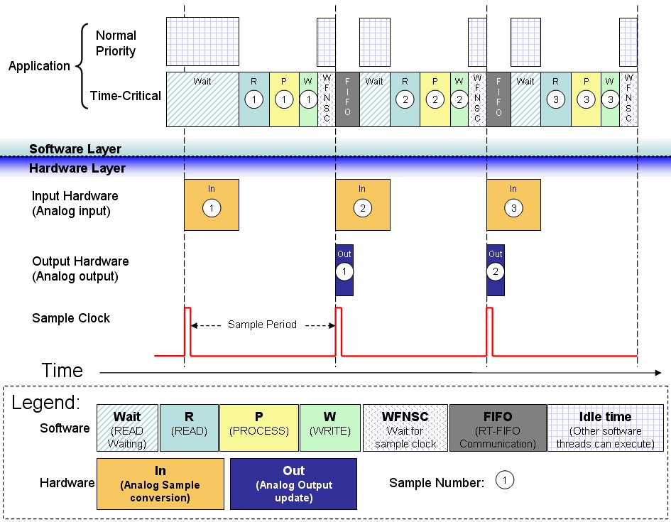
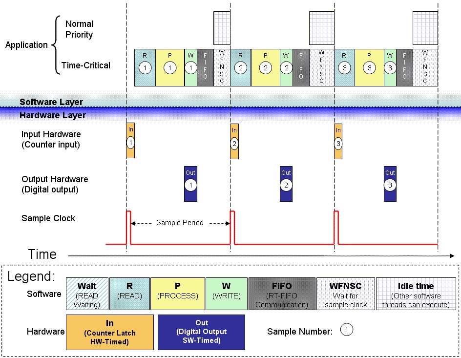
- Place the communication code (usually real-time FIFOs) after the Wait For Next Sample Clock VI.
Advantages
- The current iteration's output samples are guaranteed to be aligned with the next iteration's input samples.
- NI-DAQmx returns an error if the Wait For Next Sample Clock VI does not start before the next sample clock edge occurs.
- I/O jitter is confined to the jitter of the hardware clock, which is on the order of a few nanoseconds.
- Hardware-timed counter input operations have no conversion period similar to that of multiplexed analog input. Therefore, you can place the real-time FIFO anywhere within the LabVIEW loop.
Restrictions
Read, process, and write operations are confined to the amount of time available between the moment the device starts acquiring data and the moment the next sample clock edge arrives.
Sample Application
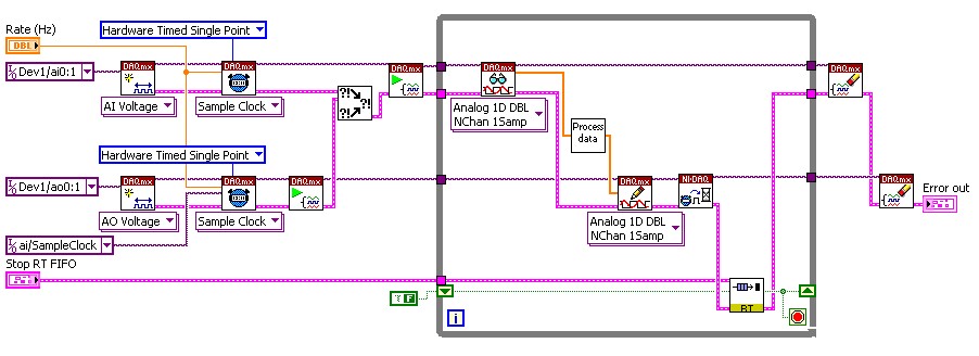
An example of this kind of application is an analog control loop that reads samples from a specific number of analog input channels, processes the data using a control algorithm (such as PID), and writes the new control values to the analog output channels. The application uses a real-time FIFO to stop the control loop based on a Boolean value provided by a lower-priority process. A similar approach can employ the use of real-time FIFOs to vary the PID parameters on the fly, or to transfer acquired and control output values to lower-priority processes for data logging and remote monitoring.
Sample Timing Diagram
Sample Implementation
- Wire the Wait For Next Sample Clock VI to one of the hardware-timed tasks. Use dataflow wiring to guarantee that the Wait For Next Sample Clock VI executes after the AO Write call.
- Use dataflow wiring to guarantee that the real-time FIFO operations execute after the Wait For Next Sample Clock VI executes.
- If the Wait For Next Sample Clock VI does not execute before the arrival of the next sample clock edge, it returns an error.
Sample Block Diagram
Notes
- Use only one Wait For Next Sample Clock VI within a LabVIEW loop. If you have multiple hardware-timed I/O tasks within the same LabVIEW loop, you can connect the Wait For Next Sample Clock VI to any one hardware-timed single-point task within that loop.
- If, when a cycle overflow occurs, you want to receive a warning rather than an error, set the DAQmx Real-Time»Convert Late Errors to Warnings property to True.
- Although you do not have to place the real-time FIFO code after the Wait For Next Sample Clock VI, it is highly recommended that you do so when dealing with multiple-channel analog input operations on multiplexed devices (such as E and M Series). Because the device can spend up to 50% of the sample period converting samples on the analog input channels, executing the FIFO code during this conversion period has the advantage of using up otherwise idle time.
- You can increase the Analog Input Conversion Rate manually through the DAQmx Timing Property Node. This reduces the total amount of time spent converting the requested number of samples. It is important to consider the minimum settling time specifications for the complete data acquisition system to avoid signal degradation and interference.
Application Case 3 - Hardware-Timed Input, Software-Timed Output
Requirement
"My analog input task needs to be hardware-timed. My output task does not need hardware synchronization with the sample clock edge."
Solution
Use the DAQmx Real-Time»Report Missed Samples property, which returns an error if new samples are available before the read operation finishes converting samples from the previous iteration.
Advantages
- Input samples are hardware-timed.
- Read, process, and write operations can overflow into the next sample period, as long as enough time remains for the subsequent read operation to complete on the next set of input samples. An application that acquires data from multiple channels on multiplexed devices (such as E Series and M Series) has to wait for the device to convert input samples before the read operation can return. By allowing process and write operations to overflow into the next sample period, the application takes advantage of otherwise idle time. This enables the application to achieve higher control-loop rates.
Restrictions
Output updates suffer from software jitter because they are not hardware-timed.
Sample Application
An example of this kind of application is an analog control loop that reads samples from a specific number of multiplexed analog input channels, processes the data using a control algorithm (such as PID), and writes the new control values to the analog output channels using a software-timed task.
Sample Timing Diagram
Sample Implementation
- Set the Report Missed Samples property for the analog input operation to True.
- The analog input operation returns an error if new samples are available before the read operation finishes converting samples from the previous iteration.
Sample Block Diagram
Notes
- If, when an Analog Input Read overflow error occurs, you prefer to receive a warning rather than an error, set the Convert Late Errors to Warnings property to True.
- Do not use the Wait For Next Sample Clock VI and the Report Missed Samples property within the same LabVIEW loop.
- Only hardware-timed single-point analog input tasks support the Report Missed Samples property.
- Because the analog output task is software timed, the value is written out as soon as the write call is initiated. It does not wait for a hardware clock to output the data.
Application Case 4 - Hardware-Timed Counter Tasks
Requirement
"I want to use hardware-timed counter input operations to drive my control loop."
Solution
Use the Wait For Next Sample Clock VI to synchronize the counter operations with the counter's sample clock.
Advantages
- Counter tasks allow for flexible timing and event detection operations that can drive the software processing of the control loop. In other words, the control loop can have a dynamic clock rate.
- NI-DAQmx returns an error if the Wait For Next Sample Clock VI is not started before the next sample clock edge arrives.
Restrictions
Read, process, and write operations are confined to the time available between the moment the device starts acquiring data and the moment the next sample clock edge arrives.
Sample Application
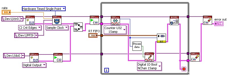
An example of this kind of application is a control loop that uses a counter input task, such as count edges, while controlling digital lines based on some predefined control logic. This sample application performs communication through the use of real-time FIFOs.
Sample Timing Diagram
Sample Implementation
- Wire the Wait For Next Sample Clock VI to the counter input task.
- If the Wait For Next Sample Clock VI does execute before the arrival of the next sample clock edge, it returns an error.
Sample Block Diagram
Sample Application 2
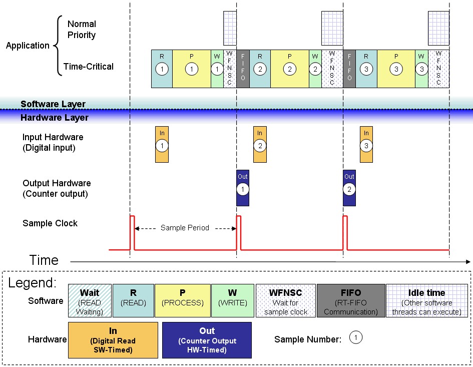
Another example application is a control loop that monitors discrete inputs and uses the values to update a counter output task, using pulse frequency mode to generate pulse-width modulation control signals. This example application performs communication through the use of real-time FIFOs.
Sample Timing Diagram
Sample Implementation
- Wire the Wait For Next Sample Clock VI to the counter output task.
- If the Wait For Next Sample Clock VI does not execute before the arrival of the next sample clock edge, it returns an error.
Sample Block Diagram
Notes
- Use only one Wait For Next Sample Clock VI within a LabVIEW loop. If you have multiple hardware-timed I/O tasks within the same LabVIEW loop, you can connect the Wait For Next Sample Clock VI to any one hardware-timed single point task within that loop.
- If, when a cycle overflow occurs, you want to receive a warning rather than an error, set the DAQmx Real-Time»Convert Late Errors to Warnings property to True.
- Hardware-timed counter operations have no conversion period similar to that of multiplexed analog input. Therefore, the real-time FIFO can be placed anywhere within the LabVIEW loop.
- NI-DAQmx provides a mechanism to recover after missing a sample clock edge when performing counter writes. If this write recovery mechanism is not successful, NI-DAQmx returns an error, and subsequent operations on that task are no longer hardware timed.
- The DAQmx Real-Time»Write Recovery Mode property allows you to choose between Wait For Interrupt or Polling mode for the recovery mechanism. Wait For Interrupt, which is the default, allows lower priority processes to execute while NI-DAQmx attempts to recover. Polling mode, on the other hand, allows for higher sampling rates.
Application Case 5 - Software-Timed I/O
Requirement
"My I/O tasks are of types that do not support hardware-timed operations."
Solution
Apply software timing to your time-critical loop by using the Timed Loop. Configure your NI-DAQmx tasks to use on demand timing.
Advantages
- Can perform I/O control loops with operations that are not hardware-timed.
- Read, process, and write operations are confined to the software timing period that you define with the Timed Loop.
Restrictions
I/O samples suffer from software jitter.
Sample Application
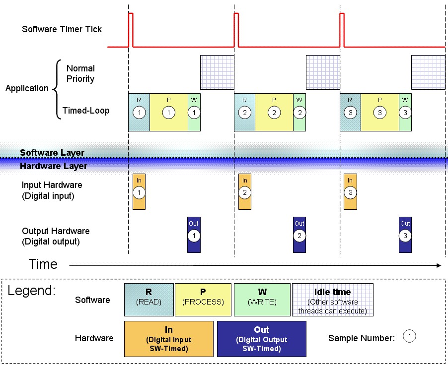
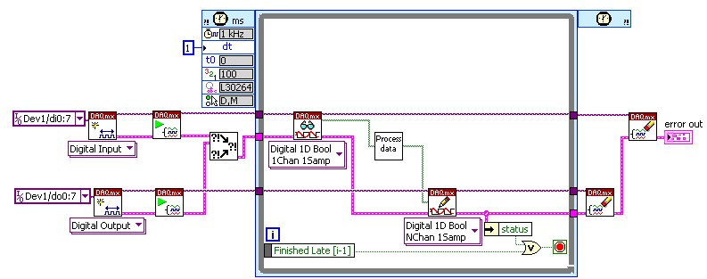
An example of this kind of application is a digital I/O control loop. The application monitors the state of several discrete inputs and toggles the corresponding output based on the control algorithm. Hardware timing is not available for single-point digital I/O tasks in NI-DAQmx.
Sample Timing Diagram
Sample Implementation
- A Timed Loop running off the system's time sources (millisecond or microsecond resolution) accomplishes the task. Configure the Timed Loop to run at the desired rate.
- Configure all tasks to be software-timed (on demand).
- The Timed Loop provides feedback to the application as to whether the previous iteration completed in time. It does this through the "Finished Late [i-1]" node.
Sample Block Diagram
Notes
- The Timed Loop allows the application to adjust its period from within the loop, allowing the implementation of dynamic timing algorithms for control.
- Lower-priority processes can execute while the Timed Loop waits until its next iteration.
- Other software timing methods include the use of the Wait and Wait Until next multiple VIs (with microsecond or milliseconds resolution). These methods provide no feedback when the application falls behind.
Application Case 6 - Hardware-Timed Simultaneously Updated I/O Using the Timed Loop
Requirement
"My I/O needs to be hardware-timed. All output values need to simultaneously update at the arrival of the sample clock edge. However, I would also like to use the Timed Loop in my application."
Solution
Use the DAQmx Create Timing Source VI to create a timing source that drives a Timed Loop that contains the I/O operations and the control algorithm.
Advantages
- Using a timing source allows you to specify an I/O signal (for example, the sample clock event) to trigger the execution of Timed Loop iterations.
- The Timed Loop provides feedback on if the iterations complete in time.
- Multi-rate applications, using distinct I/O hardware subsystems, are possible by extending this approach to multiple Timed Loops.
Restrictions
Minor increases in overhead when compared to a regular LabVIEW While Loop.
Sample Application
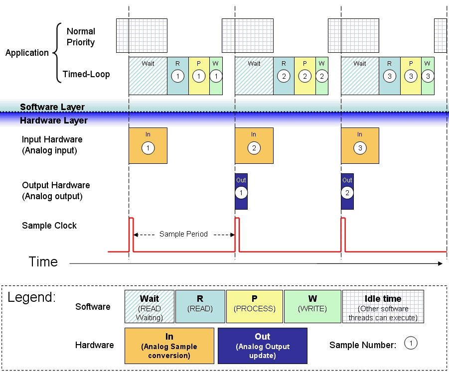
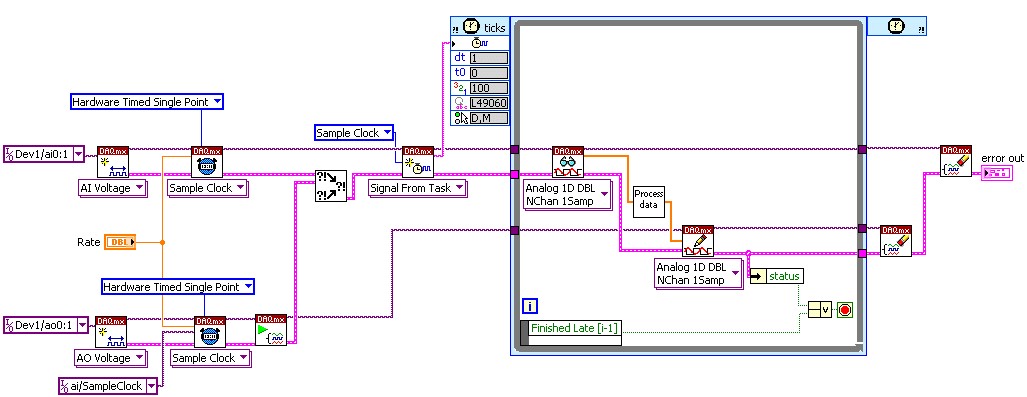
An example of this kind of application is an analog control loop that reads samples from a specific number of analog input channels, processes the data using a control algorithm (such as PID), and writes the new control values to the analog output channels.
Sample Timing Diagram
Sample Implementation
- Create a timing source for the Timed Loop by selecting a signal from the hardware-timed task. This signal is used as the timebase that drives the execution of the Timed Loop.
- The Timed Loop provides feedback to the application as to whether the previous iteration completed in time. It does this through the "Finished Late [i-1]" node.
Notes
- Lower-priority processes, including other Timed Loops with lower priorities, can execute while the Timed Loop waits until its next iteration.
- You can use the time spent converting analog input samples on multiplexed devices to perform other tasks within the loop, such as communication through real-time FIFOs.
- You can increase the Analog Input Conversion Rate manually through DAQmx Timing properties. This reduces the total amount of time spent converting the requested number of samples. It is important to consider the minimum settling time specifications for the complete data acquisition system to avoid signal degradation and interference.
- Do not use the Wait For Next Sample Clock VI for any of these tasks.

