ni.com is currently undergoing scheduled maintenance.
Some services may be unavailable at this time. Please contact us for help or try again later.
Introduction to LabVIEW Channel Wires
Overview
The channel wire simplifies the programming involved in data transfer between parallel loops, such as the common producer/consumer pattern. This document provides an introduction to channel wires and highlights specific use cases.
Contents
- What are Channel Wires?
- Channel Templates
- Uses for Channel Wires
- Use of Channel Wires with LabVIEW Real-Time
- Debugging Channel Wires
- Additional Resources
What are Channel Wires?
All wires provide a graphical representation of data flow through your program. Most wires depict synchronous flow from a source node that, when it finishes, passes its result to its sink terminal(s). Channel wires depict asynchronous data flow: data flows from a source loop while that loop is still executing to allow sink loops to start execution immediately. Channel wires abstract complex data transfer patterns to help you develop applications that run correctly with fewer mouse clicks and fewer corner cases to debug. Channels can efficiently carry any type of LabVIEW data, from simple scalar values to complex arrays, clusters, or objects.
Channel wires are meant to reduce the use of existing data transfer mechanisms such as local variables, global variables, queues and notifiers. The long-term goal is to have channel wires that remove the need for most refnum and variable programming.
We expect you will use channel wires to replace previous methods of asynchronous data transfer because:
- graphical data flow through channel wires allows you to directly see the data connections
- channel wires require fewer nodes to set up than refnums or variables
- and channel wires incorporate support for metadata signaling, such as stop and timeout, which is very complex code to write otherwise.
Older communications options remain available in LabVIEW; channel wires should replace many of their use cases but cannot replace them all. If you have an application already developed using queues, variables or other means of asynchronously transferring data, you do not have to alter your code to include channels, because other methods of asynchronous data transfer will continue to be supported. However, if you are creating a new application that incorporates two or more parallel loops, we recommend you evaluate using channel wires. Later in this white paper, channel wires will be compared to other methods like queues and variables to highlight the differences between them.
Creating a Channel Wire
Every channel wire must have at least two endpoints: a writer and a reader. You can create a channel writer endpoint or a channel reader endpoint by right-clicking a terminal or a wire and selecting Create»Channel Writer or Create»Channel Reader, then configure your Channel by choosing a template and endpoint type. Each template expresses a different communications protocol; an overview of template types is given in the Channel Templates section.
Channel Templates
LabVIEW provides channel templates that you can use to build applications. Each template expresses a different communications protocol. If you are writing a Real-Time or FPGA program, the Streams available will vary slightly (see Channel Wires in LabVIEW Help for specific templates available for RT or FPGA programs.)
Stream
A Stream channel operates like a queue: a lossless buffered Stream of values. A Stream only allows for one writer and one reader– the wire is not allowed to fork. The data in this buffer is transferred using a “first-in, first-out” (FIFO) data structure in which elements are held in the buffer and read from the buffer in the same order that they are received. An example of a Stream channel is displayed in Figure 1 below.
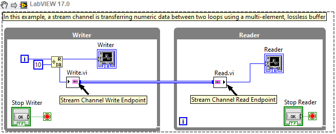
Figure 1: Stream Channel
Note: This image is a LabVIEW snippet, which includes LabVIEW code that you can reuse in your project. To use a snippet, right-click the image, save it to your computer, and drag the file onto your LabVIEW diagram.
Messenger
A Messenger channel is a buffered channel that allows for “many-to-many” communication in which sending “command-like” messages is needed. Messenger channels can have multiple writers and readers which allow for the interleaving of messages in a significant way for the reader endpoint to interpret. Figure 3 displays a Messenger channel where multiple writers interleave messages that a reader receives.
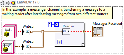
Figure 2: Messenger Channel
Tag
A Tag channel operates like a variable: a single value that code may read or write. Stated formally, a Tag incorporates a one-element, lossy buffer that allows for multiple writers and readers to access the data value most recently written to the buffer.
Tag channels can be used when your application requires that only the most recent value of data is available to waiting parallel loops, (i.e., it does not matter if previous data values are lost). An example of a Tag channel is shown in Figure 3 below.
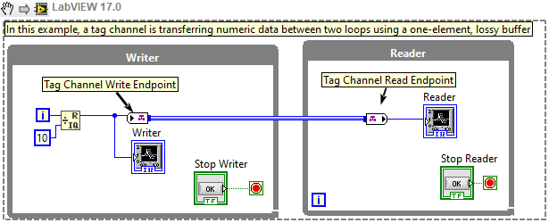
Figure 3: Tag Channel
Tag channels do not remove all of the programming dangers inherent in variable programming. You can still create “read-modify-write” race conditions using Tags. To avoid this, try to always use the Tag channels to transfer data from one loop to another loop – never have the same loop both read and write the value. Although that kind of variable-like programming seems easy, it is frequently full of hard-to-test situations that will make your program randomly go awry.
Other Channel Templates
Stream, Messenger and Tag cover most data transfer needs, but LabVIEW supplies several specialized channels:
- Accumulator Tag: A variable that tracks the sum of written values from multiple writers to be sent to multiple readers.
- High Speed Stream: A Stream channel that supports higher throughput, but lacks some of the functionality available with normal Stream channels.
- Lossy Stream: A Stream channel that allows for data loss if the buffer is full.
- One Element Stream: A Stream channel optimized for a buffer size of 1; the write endpoint waits if the buffer is full.
- Event Messenger: A channel to transfer messages from multiple writers, each write triggering an event
Based on the needs of your application, you can determine which kind of data transfer protocol is the most appropriate. For more information, refer to the examples for each channel template located at labview\examples\Channels.
Uses for Channel Wires
Channel wires provide direct graphical notation for data flow through programs in which data is transferred asynchronously. Channel wires are not a complete replacement for tools in LabVIEW like queues or variables, but they are more effective at showing how data is actually flowing through a program than previously available features.
A Stream channel, for example, clearly shows how data flows from the writer endpoint to the reader endpoint. Since all writer and reader endpoints are connected with wires, even through the connector panes of sub VIs, we need only follow the wire to identify where Stream data is flowing within our program.
Stream channels can be used in multiple instances in which queues are used; Figure 4 below displays the complexity of a very basic queue compared to a Stream channel. In the top two while loops of the block diagram, a very basic queue structure is displayed; in the bottom two loops of the block diagram data transfer between a writer and reader node of a Stream channel is displayed.
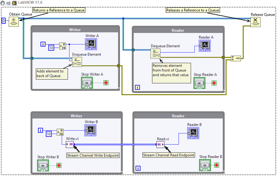
Figure 4: Use of Queue Compared to Stream Channel
With the channel, there is a clear connection between the channel writer and the channel reader, whereas the relationships between different nodes of previously available methods are not as obvious. With queue references and functions in your code, it can be difficult to follow the data flow between parallel loops and understand what is occurring within a block diagram. The data flow through Stream channels, however, is represented in a visually intuitive way; data flows from the writer node to the reader node and the lack of tunnels as a channel enters or leaves a data structure helps further reinforce the asynchronous data flow that channels provide. Queues require more nodes to set up than channels do, which increases development time and leaves more room for improperly structured code.
Use of Channel Wires with LabVIEW Real-Time
The only channel template that provides specific functionality on LabVIEW Real-Time is the Real-Time Stream channel. Use this kind of Stream channel specifically for sending data to/from a timed loop. Real-time (RT) Stream channels are built using Real-Time FIFOs and allow you to maintain determinism within your code while still abstracting away the complexity of queues, variables, etc. Building Real-Time Stream channels into start up executables that are deployed to real-time targets is supported. Figure 5 below shows the implementation of two Real-Time Stream Channels.
Figure 5: Real-Time Stream Reading from FPGA
In this program, data is being read from the FPGA of a Real-Time target using an FPGA Read/Write Control and then written to two RT Stream Channels. Both Stream channels are transferring data from a higher priority, deterministic, timed-loop to a lower priority while loop. The RT Stream Channel with the blue wire connecting its end points is transferring integer data which is then logged to disc as a text file on the RT target. The RT Stream Channel with the green wire is transferring Boolean data from the stop button on the front panel of the RT program. Since the timed loop will run at a faster rate than the while loop, data will be buffered in the Stream channel until the while loop catches up.
Debugging Channel Wires
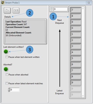
While a program is running, channel wires can be probed in order to monitor the data flowing through the wires. Once a probe is dropped, an additional window opens where you can monitor different parameters. These windows display information custom to each kind of channel. Refer to Figure 6 below for an image of what a channel probe windows looks like.
Figure 6: Channel Probe Window
The following list describes important details about the previous channel probe window:
- Monitor the elements in the queue
- View details about the current status of the Stream
- Monitor whether or not the last element has been written
