Hazardous Locations: How to Provide Explosion Protection and Create Intrinsically Safe Systems
Overview
This paper will discuss the principles of explosion protection, including the use of intrinsically safe systems, and how to successfully deploy NI equipment into these hazardous locations.
Contents
- Explosions
- Explosion Protection Standards
- Intrinsically Safe Protection
- Training and Inspections
- How to Use CompactRIO in Hazardous Locations
- Next Steps
- Appendix A: Explosion Detection Standard Details
- Appendix B: Example of Markings
Many industries, like mining, chemical and pharmaceutical plants, oil and gas, painting facilities, and metalworking operations, contain hazardous environments where fire and explosions are a major safety concern. Special techniques and designs have been developed to safely use electrical equipment in these hazardous locations.
Please note that this guide is only an overview of deploying equipment in hazardous locations. Proper training and certified personnel are required to design and deploy equipment in hazardous locations.
Explosions
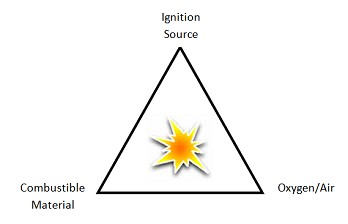
Helping understand how to prevent explosions and fires requires basic knowledge of the principals of explosions. An explosion is an exothermic reaction with a sudden rise in pressure, temperature, or both. Three factors must be present simultaneously for this reaction to take place: combustible material, ignition source, and oxygen/air. These three factors are also known as the ignition triangle. When placing equipment into hazardous environments, designers must eliminate one or more of these factors to reduce the risk of explosion to a safe and acceptable level.
Figure 1. Ignition Triangle
Combustible Material
A combustible material can be a gas, liquid, or solid (dust and fiber particles). These materials can occur naturally, such as methane gas in mines, or be produced by processes, such as aluminum powders in paint production.
Ignition Source
Ignition sources can cause a combustible material to explode or ignite. They can include any of the following:
- Hot surfaces
- Open flames
- Hot gasses
- Sparks from a mechanical process
- Electrical sparks and arcs
- Electrostatic discharges
- Lightning
- Chemical reactions
Oxygen/Air
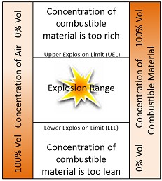
In typical hazardous location standards the oxygen/air source is air at normal atmospheric conditions. An explosion occurs only if the concentration of oxygen in the air is enough for a given quantity of combustible material. If the concentration of a combustible material is too high or too low, an explosion does not occur. The lowest concentration by percentage of volume in air that a combustible material ignites is called the lower explosive limit. Below this level the material does not ignite as the concentration is “too lean.”
The highest concentration that a combustible material ignites is called the upper explosive limit. Above this level the material does not ignite as the concentration is “too rich.”
An explosion only occurs between the lower explosive limit and the upper explosive limit.
Figure 2. Explosion Limits
Explosion Protection Standards
Key standards in North America and Europe are used when designing and deploying equipment. These standards define the hazardous locations based on type of combustible material (gas, dust, or fibers) and how often these combustible materials are present in dangerous levels. In Europe, the levels are defined in “zones” and in North America the levels are defined as “divisions.” The type of materials in North America are defined as “classes.”
In Europe, two standards/directives are used, which are based on International Electrotechnical Commission (IEC) and European Committee for Electrotechnical Standardization (CENELEC) standards:
- ATEX 137 Use Directive (99/92/EC): Site operators use this to designate hazardous environments into zones and control the three factors of explosions.
- ATEX 95 Product Directive (94/9/EC): Equipment providers, such as NI, use this to test equipment and confirm the equipment will not become an ignition source.
In North America, rules for explosion protection are defined in the United States in the National Electric Code (NEC) (NFPA 70, article 500) and in Canada in the Canadian Electric Code (CEC).
Below is a summary of the key differences between the standards. Each section is discussed in detail in Appendix A:
Table 1. Comparison of Explosion Protection Standards
| North America (NEC/NFPA 70, article 500) | Europe (ATEX 137 & 95) (IEC & CENELEC) |
Explosion Levels/Risks | Divisions (1, 2) | Zones (0, 1, 2) |
Material Type/ Equipment Ratings | Classes (I, II, III) | Equipment Group (I, II) Category (M1, M2, 1G, 2G, 3G, 1D, 2D, 3D) Equipment Protection Levels (Ma, Mb, Ga, Gb, Gc, Da, Db, Dc) |
Gas Groups | Class Gas Group (A, B, C, D) | Zone Gas Group (IIC, IIB, IIA) |
Temperature Groups | Code (T1, T2.., T3…, T4.., T5, T6) | Class (T1, T2, T3, T4, T5, T6) |
Intrinsically Safe Protection
One of the most common and effective ways to install electronics in hazardous locations is using intrinsically safe protection. Intrinsically safe systems can be deployed in hazardous locations because they provide protection based on limiting both the electrical energy and thermal energy. These systems limit this energy in both normal and abnormal operating conditions so that the electronics cannot ignite a hazardous material in the materials easiest ignitable condition. Intrinsically safe circuits can be connected and disconnected even while live because of this limitation in energy. Applicable safety standards define certain electrical characteristics that must be maintained to prevent ignition. These electrical characteristics can be found in IEC 60079-11 for Europe or UL 60079-11 for the United States. These electrical characteristics include the maximum amount of energy required to ignite various hazardous mixtures, and maximum capacitance and inductance values since the stored energy can ignite hazardous mixtures.
Intrinsically safe systems must protect in both normal and abnormal operation so that even if the electrical system is in a fault condition, the system does not ignite the hazardous material. Fault conditions could include opens, shorts, and grounding of the electrical signals, as well as higher voltage levels. Different levels of intrinsically safe systems exist depending on the Zone/Division equipment that must be employed. Type “ia” provides two layers of fault prevention and can be placed into Zone 0 environments.
Designers can choose from multiple different intrinsically safe options to deploy electronic equipment. Intrinsically safe standards allow the following three options, also known as apparatus.
Associated Apparatus
An associated apparatus is an electrical device typically installed in nonhazardous locations. It delivers a safe interface between measurement/control systems and field devices (sensors) located in hazardous locations. Barriers and isolators are two different types of associated apparatus.
Barrier
A barrier is a passive device that consists of a Zener diode, resistor, and fuse network. The main advantages of a Zener barrier include:
- Lower part cost
- Simple device
The disadvantages of a Zener barrier include:
- Requires a dedicated safety ground
- Drop in voltage provided to field sensors
- Leakage current from the Zeners affects measurement accuracy
- Requires routine checks because of the potential of permanent damage in case of fault or incorrect installation
Isolator
Another type of associated apparatus is a galvanic isolator. These devices isolate the intrinsically safe connections using transformers, optical isolators, or electro-mechanical devices. This isolator usually requires a power supply. The main advantages of a galvanic isolator are:
- Does not require a dedicated safety ground
- No voltage drop
- Better accuracy
- Grounded sensors can be used
Disadvantage:
- Higher part cost
Table 2. Comparison of Barriers and Isolators
Barrier | Isolator |
Lower cost (~$100-250 per channel) Dedicated safety ground required Voltage drop to field sensors Lower measurement accuracy Routine checks required | Higher cost (~$130-500 per channel) No ground requirements No voltage drop Better accuracy More robust to damage |
Simple Apparatus
A simple apparatus is an electrical component or combination of components with well-defined parameters that can be used in an intrinsically safe circuit. These components do not generate or store more than 1.5 V, 100 mA, and 25 mW. Examples include thermocouples, photocells, switches, junction boxes, resistors, and simple semiconductor devices.
Intrinsically Safe Electrical Apparatus
An intrinsically safe electrical apparatus is an electrical device that is designed to be directly installed in a Zone 0 or Zone 1 hazardous environment. Examples of these devices include solenoid valves and pressure transducers.
Training and Inspections
Before designing and deploying electrical systems into hazardous locations proper training needs to be completed. A variety of sources offer training throughout the world. Some training facilities include: R.Stahl, ExVeritas, and Intertek.
Depending on the location and local governing laws, inspections by approved personnel may be required. Europe requires inspections according to IEC 60079-17/14. In North America, certified NEC inspectors can be used.
How to Use CompactRIO in Hazardous Locations
CompactRIO is powered by LabVIEW reconfigurable I/O (RIO) architecture and features an open embedded architecture with extreme ruggedness and industrial I/O modules. CompactRIO is designed for applications in harsh environments and small places. Size, weight, and I/O channel density are critical design requirements in many such embedded applications. By taking advantage of the extreme performance and small size of FPGA devices, CompactRIO can deliver unprecedented control and acquisition capabilities in a compact, rugged package with extreme industrial certifications and ratings for operation in harsh industrial environments. CompactRIO is compatible with temperature ranges of -40 °C to 70 °C (-40 °F to 158 °F) and features a 50 g shock rating. The platform also maintains a variety of international safety, electromagnetic compatibility (EMC), and environmental certifications and ratings.
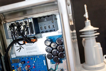
Figure 3. CompactRIO in Use
These enhanced capabilities make CompactRIO a perfect architecture for conditioned monitoring and control in hazardous locations. Out of the box, CompactRIO can be used in Division 2/Zone 2 locations. With some additional accessories such as intrinsically safe associated apparatus and explosion-proof enclosures, CompactRIO can be used in Division 1/Zone 0 or 1 locations. The following describes how to safely deploy CompactRIO in various types of hazardous locations.
Division 2/Zone 2
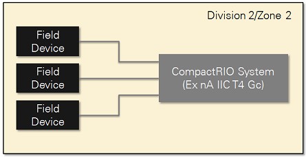
Most CompactRIO products are tested and rated safe to use in Division 2/Zone 2 environments and to interface with field devices rated for Division 2/Zone 2. Please refer to the product certification page on ni.com to see which products are rated.
Figure 4. Division 2/Zone 2 Installation
Division 1/Zone 0/Zone 1
When the electronics need to interface to or be installed in more restricted divisions or zones, CompactRIO systems can be deployed with additional equipment and protection.
Connecting to Division 1/Zone 0/Zone 1 Devices
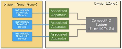
CompactRIO can be installed in Division 2/Zone 2 hazardous locations and connect to a Division 1/Zone 0/Zone 1 device through an approved intrinsically safe associated apparatus. Either a Zener barrier or galvanic isolator can limit the amount of energy provided to or from the sensors. Companies like Phoenix Contact (MACX isolator products) and R Stahl (Safety Barriers Series 9001/9002/9004 products and ISpac Isolator products) sell these associated devices.
Figure 5. Interfacing to Intrinsically Safe Field Devices
Connecting to Division 1/Zone 0/Zone 1 Devices
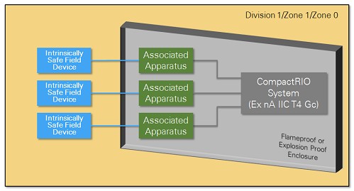
CompactRIO can be installed in Division 1/Zone 0/Zone 1 hazardous locations and connect to a Division 1/Zone 0/Zone 1 device through an approved intrinsically safe associated apparatus and the use of an explosion-proof or purged enclosure. Either a Zener barrier or galvanic isolator can limit the amount of energy provided to or from the sensors. Companies such as Phoenix Contact (MACX isolator products) and R Stahl (Safety Barriers Series 9001/9002/9004 products and ISpac Isolator products) sell these associated devices. Companies such as R Stahl sell purged and explosion-proof enclosures.
Figure 6. Installing CompactRIO in Division 1/Zone 1/Zone 0 Locations
Next Steps
As you can see CompactRIO is an ideal architecture to use in some of the harshest conditions, including possible hazardous locations subject to explosive conditions. Whether you are deploying in an oil and gas field or a mine, CompactRIO can meet your needs.
Learn more about the CompactRIO product line.
Explore these case studies about deploying CompactRIO in hazardous locations:
Oil Well Fracture Pump Monitoring and Analysis Using LabVIEW and NI RIO Technology
Appendix A: Explosion Detection Standard Details
European/ATEX Locations
Groups and categories define the environment that equipment may be placed into.
Equipment Group I:
Equipment that can be used in mining facilities (below and above ground) where explosive gases and/or dust may exist. Equipment Group I is further divided into Categories M1 and M2.
Table A‑1. Equipment Group I Definition
Equipment Category | Category M1 | Category M2 |
Equipment Protection Level (EPL) | Ma | Mb |
Definition | Equipment has a very high degree of safety and may operate in explosive environment | Equipment has a high degree of safety but must be turned off before entering explosive environment |
Equipment Group II:
Equipment that can be used in other areas where explosive environments may exist. Equipment Group II is further divided into Categories 1, 2, and 3. These categories are sometimes called zones.
Table A‑2. Equipment Group II Definition
|
| Category 1 | Category 2 | Category 3 |
Gas Protection | Equipment Category | 1G | 2G | 3G |
Equipment Protection Level (EPL) | Ga | Gb | Gc | |
Zone | 0 | 1 | 2 | |
Definition | Areas containing explosive concentrations of gas or vapor continuously or occasionally under normal conditions | Areas containing explosive concentrations of gas or vapor occasionally under normal conditions | Area where explosive concentrations of gas or vapor is not likely in normal operation | |
Dust Protection | Equipment Category | 1D | 2D | 3D |
Equipment Protection Level (EPL) | Da | Db | Dc | |
Zone | 20 | 21 | 22 | |
Definition | Areas containing explosive concentrations of dust continuously or occasionally under normal conditions | Areas containing explosive concentrations of dust occasionally under normal conditions | Area where explosive concentrations of dust is not likely in normal operation |
North American Locations
Classes and divisions are used to define hazardous areas:
Table A‑3. North American Division and Class Definitions
| Class I (Flammable gas or vapors) | Class II (Combustible dust or powder) | Class III (Combustible fibers) |
Division 1 | Areas containing explosive concentrations of gas or vapor continuously or occasionally under normal conditions | Areas containing explosive concentrations of dust or powder continuously or occasionally under normal conditions | Areas containing explosive concentrations of fibers continuously or occasionally under normal conditions |
Division 2 | Area where explosive concentrations of gas or vapor is not likely in normal operation (will only persist for a short time if present) | Area where explosive concentrations of dust is not likely in normal operation (will only persist for a short time if present) | Area where explosive fibers are not likely in normal operation (will only persist for a short time if present) |
Comparison of European and North American Locations
Below is a comparison of the division method to the three-zone method. For the most part, the two systems are equivalent with some minor differences.
Equipment designed for Division 1 includes features that would allow it to be used in Zone 0/20, however equipment designed for Zone 1/21 can’t typically be used in Division 1 areas. Class III material is handled in Zone 20, 21, and 22 in the European system.
Table A‑4. Comparison of Division and Zones
Method | Continuous Risk (1,000 hours per year or more/10%) | Occasional Risk (10-1,000 hours per year/0.1-10%) | Risk Not Likely (10 hours or less per year/0.01-0.1%) |
Divisions (North America) | Division 1 | Division 2 | |
Zones (Europe) | Zone 0/20 | Zone 1/21 | Zone 2/22 |
Table A‑5. Comparison of Gas Groups
Gas | Class Gas Group (North America) | Zone Gas Group (Europe) |
Acetylene | A | II C |
Hydrogen | B | |
Ethylene | C | II B |
Propane | D | IIA |
Temperature Classes
Ignition temperature is the lowest temperature at which a material ignites without another source of ignition, such as a flame. The surface temperature of equipment in hazardous locations must be kept below this ignition temperature for the particular combustible material that is present. Hazardous location rated equipment is marked with a temperature code/class which designates the maximum surface temperature during operation when operating in its rated maximum ambient temperature.
Table A‑6. Temperature Classes
Code/Class | Maximum Temperature °C | Maximum Temperature °F |
T1 | 450 | 842 |
T2 | 300 | 572 |
T2A* | 280 | 536 |
T2B* | 260 | 500 |
T2C* | 230 | 446 |
T2D* | 215 | 419 |
T3 | 200 | 392 |
T3A* | 180 | 356 |
T3B* | 165 | 329 |
T3C* | 160 | 320 |
T4 | 135 | 275 |
T4A* | 120 | 248 |
T5 | 100 | 212 |
T6 | 85 | 185 |
*only applicable to the North American Temperature Code
Protection Methods
Different methods exist to protect equipment so that it does not cause an explosion in a hazardous location. These methods differ depending on the location where the equipment is being installed and what is being connected to the equipment.
Table A‑7. Protection Methods
Gas Method of Protection | Applicable Location | Definition |
Flame Proof or Explosion Proof | “d” Flame proof-Zone 1 Explosion proof-Zone 1 and Div 1 | An enclosure that can withstand an explosion that may be caused by a spark, high temperature, or electrical fault. |
Increased Safety | “e” for Zone 1 | Electrical equipment designed not to produce arc or sparks or to exceed high temperatures. |
Intrinsic Safety | “ia” for Zone 0 “ib” for Zone 1 and 2 | Electrical equipment designed so that the electric circuits cannot ignite combustible material. |
Encapsulation | “ma” for Zone 0 “mb” for Zone 1 | Parts that can ignite a combustible material are enclosed in a potting material. |
Oil Immersion | “o” for Zone 1 | Electrical equipment is immersed in a protective oil to prevent it from coming into contact with an explosive atmosphere. |
Pressurization | “px” for Zone 0 “py” for Zone 1 “pz” for Zone 2 | Prevents an explosive atmosphere from coming into contact with electrical equipment by maintaining a positive pressure in the enclosure. Clean air or an inert gas maintains pressure. |
Powder filling | “q” for Zone 1 and 2 | Filled with powder to prevent ignition. |
Non-sparking Equipment | “nA” for Zone 2 | Non-sparking devices with low temperature. |
Enclosed switch | “nC” for Zone 2 | Protected contacts. |
Restricted Breathing | “nR” for Zone 2 | Housing used to prevent a gas from entering, |
|
|
|
Appendix B: Example of Markings
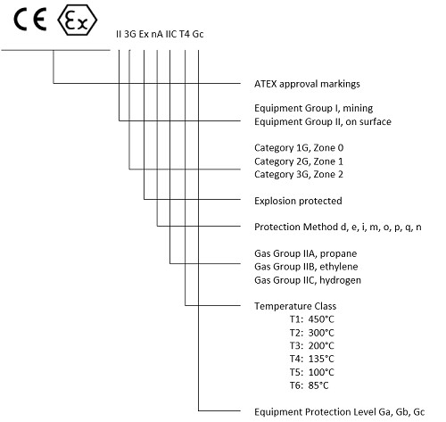
European Markings:
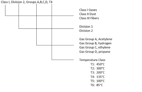
North American Markings:
