Multisim Templates for Custom Arduino Shields
Overview
Contents
Introduction
Users of Arduino boards that need to design custom shields can now accelerate the development by using predefined templates in Multisim and Ultiboard. Each template includes a Multisim schematic with connectors to define inputs and outputs and also an Ultiboard layout with the pin mapping and board outline.
Here is a list of the templates available:
- Arduino Uno
- Arduino Due
- Arduino Pro
- Arduino Ethernet
- Arduino Leonardo
- Arduino Mega 2560
- Arduino MEGA ADK
- Arduino Micro
- Arduino Mini 05
Please note that although these files are intended to be as accurate as possible and have been checked by Applications Engineers at NI, it is recommended to closely check the documentation provided with the hardware purchase. It is always suggested that you reference materials associated with the hardware to verify correct pin assignments and to check correct layout guidelines and pin spacing.
Requirements
Software
You will require Circuit Design Suite (Multisim and Ultiboard) version 13.0 (or later) to be able to utilize the attached resources.
Templates and Component Library
Go to the Downloads section and download the arduinotemplates.zip file. Unzip this file. You will find a component library (UsrComp.usr) with custom symbols and footprints and all the template files (*.mst13 extension).
To install the component library:
- Launch Multisim.
- Select Tools»Database»Merge database.
- Select your User Database as the Target database.
- Click on the Select a Component Database Name button
- Browse the UsrComp.usr database file, and click on Open.
- Click on the Start button.
- Select the Auto-Rename option.
- Click on OK.
- Once status is "Done" click on the Close button
Using the Templates
Follow the next steps to use the template files to create custom Arduino shields with Multisim and Ultiboard.
- Launch Multisim.
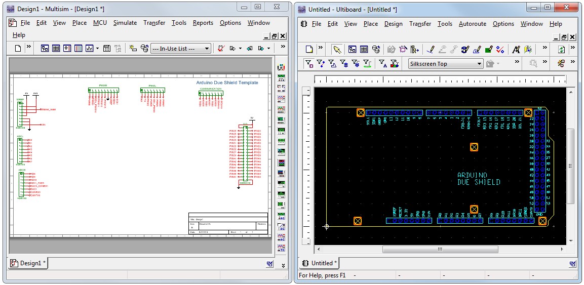
- Go to File»Open and select one of the template files. For this example we will use the Arduino Due Shield Template.mst13. If experiencing problems importing the templates, please consult the KnowledgeBase article below. Multisim unpacks the contents of the template and creates a schematic in Multisim and a layout in Ultiboard, as shown below:
Error Importing Arduino Template in NI Multisim™
Figure 1. Arduino shield template in Multisim and Ultiboard
The Multisim schematic includes all the necessary connectors for the various input/output pins. On the other hand the Ultiboard file includes the board outline and footprints of the connectors placed at specific coordinates.
- Save both the Multisim and Ultiboard files using the same name.
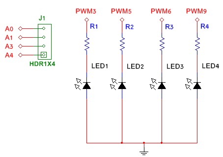
- Capture your custom circuitry in Multisim. Note that you can use On-page connectors (Place»Connectors) to create virtual connections to the appropriate pins, as shown in Figure 2.
Figure 2. Capturing your schematic in Multisim
Once you have completed your schematic you will update the changes to the layout by using Forward Annotation.
- Select Transfer»Forward annotate to Ultiboard»Forward annotate to Ultiboard 13.0.
- Save the netlist (*.ewnet) file.
- Review the changes in the Forward Annotation window and click OK. Parts will be placed outside of the board outline.
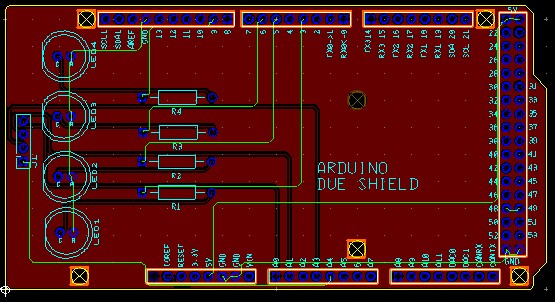
- Place the parts and route the board.
Figure 3. Arduino shield design in Ultiboard
If you need to make any changes to your design simply open the Multisim schematic, make the changes and use Forward Annotation to update the layout.
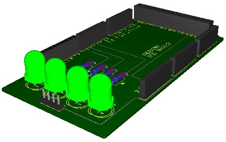
Finally, here is a 3D View of the custom shield. You can open this view by selecting View»3D Preview.
Figure 4. 3D View of the custom board


