Cascading the Outputs of the NI PXI-4130 Source Measure Units
Overview
Constant Voltage Mode: Series Cascading for Higher Output Voltage
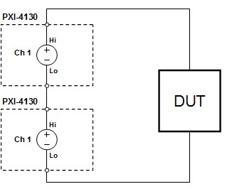
Because channel 1 on the NI PXI-4130 is an isolated output, it can be cascaded in series with other output channels to generate larger output voltages. Care should be taken that the output voltage of the SMU does not exceed the channel-to-earth ground specification of +/- 60 VDC. This means any output terminal of any PXI-4130 must always remain within +/-60 VDC from earth ground. Up to three PXI-4130s can be stacked in series to be within the +/- 60 VDC isolation without any external circuitry required. Figure 1 shows how to connect two PXI-4130s in series to achieve +/- 40 V with 2A capability:
Figure 1. Two PXI-4130s in series providing a 40V supply (both SMUs in constant voltage mode)
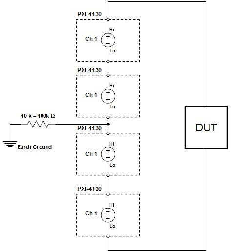
Since the isolation voltage extends from -60 VDC to +60 VDC, it is also possible to achieve a differential voltage up to 120V by connecting the center of two stacked PXI-4130s to earth ground. The connection can be tied directly to earth ground or through 10k -100k ohm resistor. This ensures that no output on any SMU will exceed the +/- 60 VDC isolation limit. Figure 2. shows four SMUs stacked with the center connection tied to earth ground through a resistor. Note, that the Hi terminal on the top PXI-4130 will be +40 VDC from earth ground and the Lo terminal on the bottom PXI-4130 will be -40 VDC from earth ground, maintaining +/- 60 VDC isolation limit.
Figure 2 . Four PXI-4130s in series with center outputs connected to earth ground providing -40V to +40V (80V differential) at 2A sinking (all SMUs in constant voltage mode)
Constant Current Mode: Series Cascading for Higher Output Voltage
If the application requirement is to create a current source with higher voltage levels than an individual SMU can provide, it is possible to place two SMU channels in series with one configured in voltage mode and the other configured in current mode. By setting one SMU in current mode and the other SMU in voltage mode, the combined supply still acts as a current mode supply. Setting both SMUs in current mode is not desired because it's then possible that the voltage dropped by each SMU will not be equal. One SMU may drift upwardly to drop the majority of the voltage while the other SMU may drift downwardly to drop a minimum voltage. Load balancing becomes particularly important when sinking power into the PXI-4130 because each device has a maximum power dissipation of 10 W.
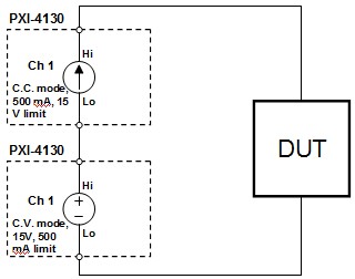
As an example, suppose a 500 mA supply with a voltage limit of 30 V is required. To achieve these settings, two PXI-4130s may be stacked and configured such that they each sink or source 7.5 W at 15 V.
Even with one supply configured in voltage mode, the supply still operates in constant current mode because the current level is maintained by the other SMU operating in current mode. Refer to Table 1 and Figure 3 below for configuration of both PXI-4130s.
| SMU | Mode | Setpoint | Limit |
| SMU 1 (channel 1) | Constant Current | 500 mA | 15 V |
| SMU 2 (channel 2) | Constant Voltage | 15 V | 500 mA |
Table 1. Configuration settings for two PXI-4130s operating in constant current mode
Figure 3. Two PXI-4130s in series acting as a 500 mA current supply with 30 V limit
Whenever stacking SMUs in series it is best practice to use the top SMU in the stack to perform the current measurements. Although the SMUs are all in series and should ideally see the same current, there could be a small common mode current that flows through the lower SMU that capacitively couples back to earth ground. Therefore, for best measurement performance possible, the top SMU is preferred for current measurements.
Constant Voltage & Current Mode: Parallel Cascading for Higher Current
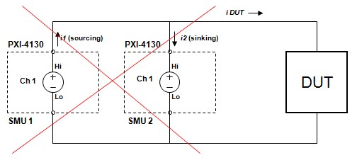
When two supplies in parallel are programmed at the same voltage level, minor variations in the circuitry among all channels prevent their voltage levels from being exactly identical. Because channel 1 of the PXI-4130 is a four-quadrant supply these minor variations could cause one channel to attempt to control another, resulting in undesired behavior or mismatch among the current supplied by the channels. One SMU output may begin to sink the current provided by the other SMU instead of being directed to the DUT. In Figure 4 below, if each SMU is expected to provide 2 A to the DUT (4 A total) then i DUT = i1 + i2 = 4 A. However, if SMU 2 begins sinking current from SMU 1, then the net current to the DUT is no longer 4 A but rather i DUT = i1 - i2 < 2 A. When this occurs, the SMUs no longer work together to provide the necessary 4 A of current to the DUT.
Figure 4. Two PXI-4130s in parallel acting adversely: SMU 2 sinks the current provided by SMU 1
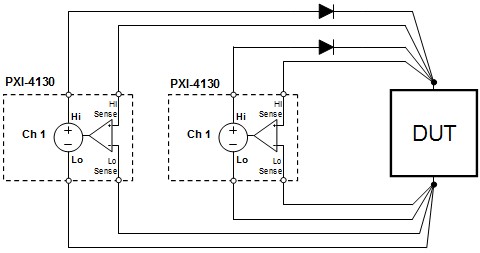
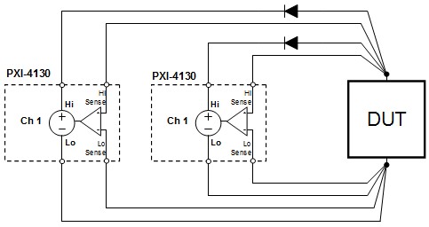
Fortunately, this undesired behavior can be avoided by using diodes on the output of each SMU channel to steer the current in one direction. To cancel out the 0.3-0.7 V that will appear across the diode, remote sense can be connected directly across the DUT terminals to ensure the correct programmed voltage appears on the DUT. Figure 5 shows two PXI-4130s configured together to provide sinking or sourcing of positive current in voltage mode.
Figure 5. Two PXI-4130s in parallel sinking/sourcing of higher positive current
Similarly, Figure 6 shows the same configuration but with the diodes reversed to allow sinking or sourcing of negative current in voltage mode. For current mode operation, Figures 5 and 6, are wired identically; however the SMUs will need to be programmed for current mode instead of voltage mode. Also note, when using remote sense, the voltage accuracy specification increases marginally by +/- 120 uV per volt of lead drop. See PXI-4130 Specifications for more details.
Figure 6. Two PXI-4130s in parallel sinking/sourcing higher negative current
Summary
Because of the isolated channel design, multiple NI PXI-4130 Power SMU channels can be combined to cover high voltage or current points than provided by a single SMU channel. Although examples discussed in this article are commonly used, it is recommended that user always test a particular combination of SMUs with a given load to ensure system stability and performance.
