NI SwitchBlock Hardware Architecture
Overview
The customizable hardware design of the NI SwitchBlock makes it easy to create large switch matrices in PXI while minimizing wiring, simplifying connectivity, and providing a high degree of flexibility for your switching needs. This paper explores the architecture that enables clean column expansion both inside and outside the NI SwitchBlock carrier as well as some of the design decisions you can make to optimize the performance of your system while maintaining a safe switching environment.
This paper is part of the Getting Started with the NI SwitchBlock series.
Download the entire Getting Started with the NI SwitchBlock white paper series
Contents
- NI SwitchBlock Carrier and Relay Cards
- Optimizing Your NI SwitchBlock Configuration
- Multicarrier Column Expansion
- Multichassis Column Expansion
- Safety Interlock System
- Related Links
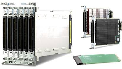
Figure 1. With the NI SwitchBlock, you can build a custom high-density switch for your application.
NI SwitchBlock Carrier and Relay Cards
The NI SwitchBlock comprises a 4-slot PXI carrier that can hold up to six 1-slot relay cards. The carrier features a hybrid-compatible connector on the back of the second PXI slot and six virtual device engines for timing and synchronization. Relay cards are available with a variety of relay types in matrix topologies.
Figure 2. Front and Rear View of the NI SwitchBlock Carrier
| Relay Card | Relay Type | Matrix Dimensions | Max Voltage (V) | Max Current Switching (Carry) | Max Switching Power (W) | Relay Card Slots Used |
| NI 2810 | Reed | 4x43 | 150 | 1 (1) A | 20 | 1 |
| NI 2811 | Reed | 8x21 | 150 | 1 (1) A | 20 | 1 |
| NI 2812 | Reed | 16x9 | 150 | 1 (1) A | 20 | 1 |
| NI 2813 | Reed | 2-Wire 4x21 | 150 | 1 (1) A | 20 | 1 |
| NI 2814 | Reed | 2-Wire 8x9 | 150 | 1 (1) A | 20 | 1 |
| NI 2815 | Reed | 4x86 | 100 | 0.25 (0.3) A | 3 | 1 |
| NI 2816 | Reed | 8x46 | 100 | 0.25 (0.3) A | 3 | 1 |
| NI 2817 | Reed | 16x22 | 100 | 0.25 (0.3) A | 3 | 1 |
| NI 2833 | Latching Electromechanical Armature | 2-Wire 4x71 | 100 | 2 (2) A | 60 | 2 |
| NI 2834 | Latching Electromechanical Armature | 2-Wire 8x34 | 100 | 2 (2) A | 60 | 2 |
Table 1. NI SwitchBlock Relay Card Offering
Mix and Match Relay Cards
You can fill the NI SwitchBlock carrier with any combination of relay cards to be used as individual matrices or combine relay cards of the same type to form a larger matrix linked together through the analog bus of the backplane of the carrier. For example, you can create a system with four NI 2815 relay cards combined to create a 4x344 1-wire, 0.25 A matrix and add a single NI 2833 to add a 4x71 2-wire, 2 A matrix. In this example, the four NI 2815 relay cards are combined using the analog bus, so the NI 2833 cannot connect to the analog bus and must be used independent of the NI 2815 relay cards.
Column Expansion
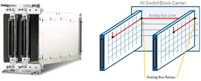
The backplane of the carrier features 16 analog bus lines that you can use to route signals between relay cards. Analog bus relays are located between the rows of the relay cards and the backplane of the carrier to connect each row of each card to the backplane.
Figure 3. You can route signals between relay cards through the analog bus of the carrier.
Optimizing Your NI SwitchBlock Configuration
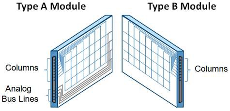
Each relay card is available in a Type A and Type B configuration. The connector on the Type A card provides access to the columns of the relay card as well as the analog bus of the carrier. To minimize the effect on the bus, Type B cards do not connect the analog bus to the front panel, and only the columns are provided for user connection. These cards have much less impact on bus performance at the expense of analog bus connectivity. The rows of the relay cards are accessible indirectly through the analog bus lines on the Type A cards. To optimize bandwidth, the number of type A relay cards should be minimized in NI SwitchBlock configurations.
Figure 4. Relay cards are available in two configurations to optimize bandwidth.
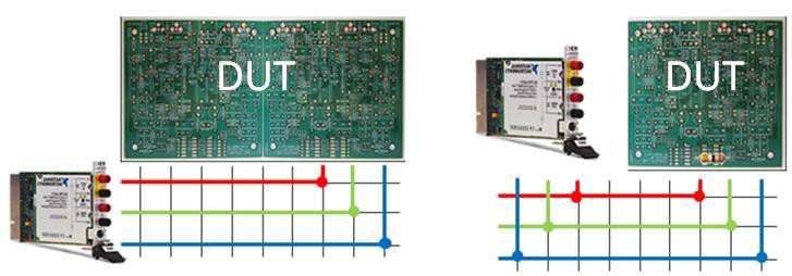
Row-to-column signal routing requires a Type A relay card to provide access to the analog bus lines of your NI SwitchBlock system. By contrast, column-to-column signal routing is possible with Type A and Type B modules. The NI SwitchBlock can be configured for either row-to-column or column-to-column signal routing.
Figure 5. Row-to-Column Signal Routing (left); Column-to-Column Signal Routing (right)
Multicarrier Column Expansion
The NI SwitchBlock carrier features expansion connectors on the left and right sides that, when joined with NI 2806 expansion bridge cards and additional carriers, allow for a continuous analog bus inside the PXI chassis (up to four carriers in 16 PXI slots holding 24 relay cards). The connectors on the expansion bridge include serial links to enable automatic identification of adjacent carriers and installed bridge cards. The flexibility to add more carriers as needed makes it possible to create matrices with more than 8800 crosspoints in a single PXI chassis.
| Relay Card | Individual Relay Card | Single Carrier Filled with Six Cards | Single PXI Chassis Filled with Four Carriers |
| NI 2810 | 4x43 | 4x258 | 4x1032 |
| NI 2811 | 8x21 | 8x126 | 8x504 |
| NI 2812 | 16x9 | 16x54 | 16x216 |
| NI 2813 | 2-Wire 4x21 | 2-Wire 4x126 | 2-Wire 4x504 |
| NI 2814 | 2-Wire 8x9 | 2-Wire 8x54 | 2-Wire 8x216 |
| NI 2815 | 4x86 | 4x516 | 4x2064 |
| NI 2816 | 8x46 | 8x276 | 8x1104 |
| NI 2817 | 16x22 | 16x132 | 16x528 |
| NI 2833 | 2-Wire 4x71 | 2-Wire 4x213 | 2-Wire 4x852 |
| NI 2834 | 2-Wire 8x34 | 2-Wire 8x10² | 2-Wire 8x408 |
Table 2. By combining relay cards in the NI SwitchBlock, you can build very large matrices.
Figure 6. You can route a signal between carriers using the NI 2806 expansion bridge (left). You must remove the analog bus cover before inserting the expansion bridge (right).
Multichassis Column Expansion
In multichassis systems, you can use Type A relay cards to extend the analog bus lines from one PXI chassis to another. To optimize bandwidth, you should place Type A relay cards in the center of NI SwitchBlock configurations.
Figure 7. You can use Type A relay cards to extend analog bus lines between PXI chassis.
Safety Interlock System
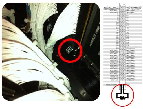
NI SwitchBlock cards require the use of a safety interlock resistor, without which you cannot route signals to or from the analog bus.
Front-Panel Cable Detection
To prevent the front connectors of NI SwitchBlock cards from exposing high-voltage signals when disconnected from NI SwitchBlock accessories, the cards detect whether a cable or other accessory is attached to the front connector. NI accessories for the NI SwitchBlock connect Pin 96 to Pin 48 through a 500 Ω resistor (500 Ω ±20 percent, 1/10 W minimum) built into the accessory. If the resistor does not connect these two pins, no matrix lines can connect to the analog bus.
Creating Custom Test Fixtures
If you create your own cable or custom test fixture for your NI SwitchBlock, incorporate the interlock resistor into your design to ensure that your signal lines are touch-safe when the test fixture or cable is removed. Additionally, incorporating the safety interlock resistor allows the operation of an integrated relay test when your fixture is disconnected.
Figure 8. Safety Interlock Resistors Connected on an ITA in a Mass Interconnect Solution
