NI Connector Reference Library for Multisim & Ultiboard
Overview
This document provides engineers with a group of connectors (symbols and landpatterns/footprints) for you to define custom circuitry, breakout boards, user defined modules and daughter cards for NI hardware.
These symbols and footprints for NI circuit design tools represent common interface connectors to NI DAQ, Single-Board RIO and CompactRIO.
All symbols and footprints for these connectors are free for you to use in NI Multisim capture (schematic symbols), and NI Ultiboard layout (footprints). By leveraging these resources, you can quickly and easily build custom hardware that interface complex signals to your prototypes.
Contents
- Why do I need these Connectors?
- Resource Content
- NI Hardware Connectors
- Installing your Database Update
Why do I need these Connectors?
Defining symbols and footprints for hardware specific connectors can be both time consuming and difficult. Ensuring that pin spacing, mapping and dimensions are all correct can take as much as a few hours to design.
Engineers who use NI hardware products must sometimes expand their hardware needs outside of off-the-shelf parts. For example it may be necessary to take the output from a DAQ card, and use a break-out board to break out each individual signal for specific use. For prototyping platforms such as CompactRIO or Single-Board RIO, you may need to create some form of accessory such as a C-Series Module, or daughter card, which will allow you to do perform additional conditioning upon a signal.
Due to the custom nature of such designs, you need access specific connectors. Much of this information can be found within datasheets, but can be difficult to either read, or time consuming to create manually. As such the ability to have these connectors in a readily available form – ready to use within your NI Multisim and NI Ultiboard design tools - can significantly aid the design process.
Support of Connectors
These connectors have been made available through our Applications Engineering and Marketing department, however are not supported components. They can assist you in completing your design needs, but are not a product to be purchased or supported through Technical Support, as an individual product.
Software Requirements
You will require the Circuit Design Suite software (containing Multisim and Ultiboard) to be able to utilize the attached resources. You can download an evaluation edition of Multisim and Ultiboard at the following online destination.
To learn more about licensing options please visit the following link.
Resource Content
In this zipped folder attached to this document (8215_connector_lib.zip) you fill find the following resources:
- ... Database/NI_Hardware_db.prz: This Multisim database file contains symbols for the connectors.
- ... Database/NI_Hardware_db.usr: This Ultiboard database file contains footprints for the connectors.
- … Datasheets/*.pdf: You will find attached a folder of datasheets for the corresponding connectors
- … Files/NI Hardware Connectors.ewprj: Ultiboard file containing the landpattern of each associated connector (as well as the 3D image)
NI Hardware Connectors
| Connector | Details | Image |
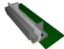
Conn_68pin_DAQ_SCSI_Male_RA Part Number: 777600-01 (connector + screw jack socket) |
|  |
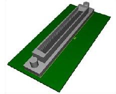
Conn_68pin_DAQ_SCSI_Male_VERT Part Number:777601-01 (connector + screw jack socket) |
|  |
Conn_100pin_SCSI_Female_Vert Part Number: 777779-01 |
| 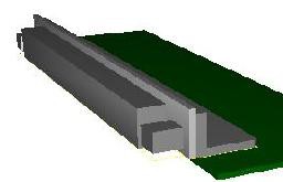 |
Conn_68pin_VHDCI_RCPT_RA Part Number: 785633-01 (connector + screw jack socket) |
| 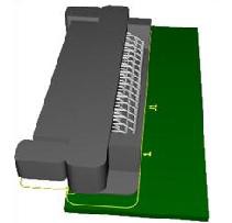 |
Conn_68pin_VHDCI_RCPT_RA_DUAL Part Number: 785634-01 (connector + screw jack socket) |
| 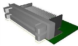 |
Conn_68pin_VHDCI_RCPT_VERT Part Number: 785753-01 (connector + screw jack socket) |
| 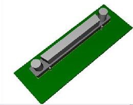 |
CONN_96pin_DIN_FEMALE_RA Part Number: 777687-81K (as a kit - kit includes connector + mechanical enclosure and strain relief) |
| 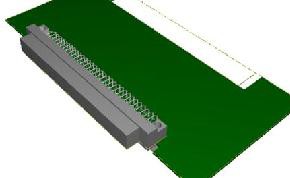 |
| CONN_32pin_DIN_FEMALE_RA |
| 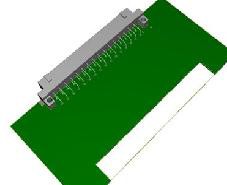 |
| CONN_50pin_DSUB_MALE_VERT |
| 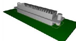 |
| CONN_37pin_DSUB_FEMALE_RA |
| 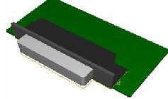 |
| CONN_50pin_IDC_MALE_VERT |
|  |
| Conn_50pin_IDC_Female_Vert |
| 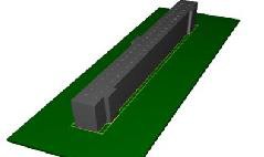 |
| Conn_50pin_IDC_Latch_Male_Vert |
| 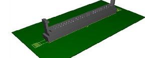 |
| Conn_34pin_IDC_Female_Vert |
| 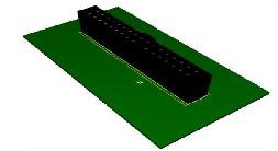 |
| Conn_176pin_HD_RA |
| 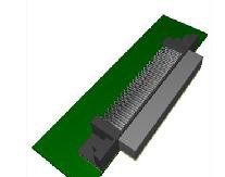 |
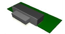
| Conn_25pin_Infiniband_4x |
|  |
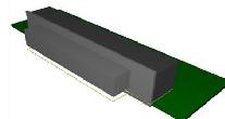
Conn_73pin_Infiniband_12x Part Number: 779157-01 |
|  |
Connectors Format
Each of the connectors included in this online resource have generic pin mappings. This means although the connector landpattern are defined accurately for physical shape, size and format (all to IPC standards), the specific pin names for each individual connector are not contained.
For additional information on the specific pin names for each ‘product’ please consult the product specific links above to see pin mappings.
Installing your Database Update
To install the attached custom connectors (from 8215_connector_lib.zip)in your database:
Multisim:
- Open Multisim ( Start > All Programs > National Instruments > Circuit Design Suite 10.1 > Multisim 10.1).
- Double-click on the NI_Hardware_DB.prz file.
- In the Database Merge dialog box select User Database as the Target Database
- Click on the Start button.
- Once status is "Done" click on the Close button.
Ultiboard:
- Open Ultiboard (Start > All Programs > National Instruments > Circuit Design Suite 10.1 > Ultiboard 10.1).
- Select Tools > Database > Merge Database…
- Select the User Database as the Target Database
- Click on Select a Component Database Name button
- Browse to the NI_Hardware_db.usr database file, and click on Open.
- Click on the Start button.
- Select the Auto-Rename option.
- Click on OK.
- Once status is "Done" click on the Close button.
Using the Components
To view these connectors in Multisim, simply:
- Open Multisim (Start >> All Programs >> National Instruments >> Circuit Design Suite 10.1 >> Multisim 10.1).
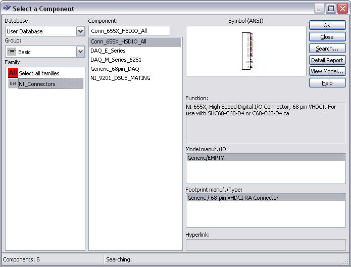
- Open the database interface (Place >> Components).
- Select the User Database in the database field.
- Select the Basic group in the group field.
- Select the NI_Connectors family.
You can now place any of the connector components, by selecting the component and clicking on OK.
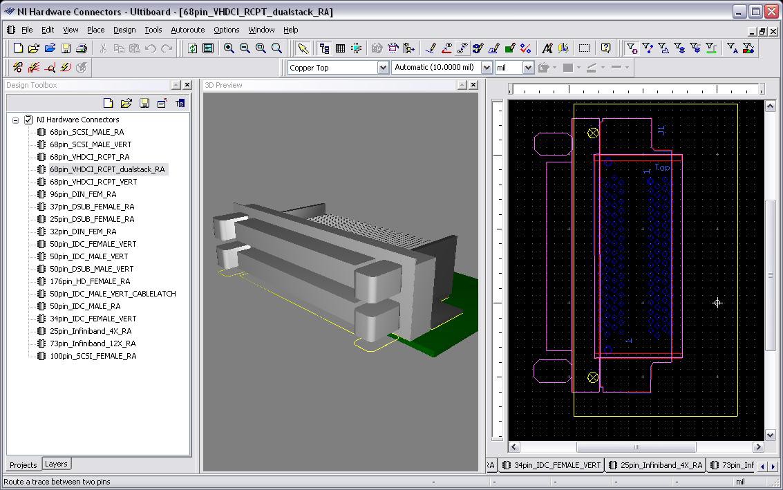
You can also open the attached Ultiboard file (...Files/NI Hardware Connectors.ewprj), and view the landpattern and 3D image for each of these landpatterns:
- Open Ultiboard (Start >> All Programs >> National Instruments >> Circuit Design Suite 10.1 >> Ultiboard 10.1).
- Select File > Open
- Browse to the NI Hardware Connectors.ewprj file
- Click on the Open button
- Select View > 3D Preview
You will now see a multiple layout project which shows the landpattern and 3D view of each NI hardware connector.
