NI does not actively maintain this document.
This content provides support for older products and technology, so you may notice outdated links or obsolete information about operating systems or other relevant products.
An electrocardiogram (ECG) is a graph produced by an electrocardiograph that provides information about an individual’s cardiac health. Doctors commonly use ECGs in clinical applications to diagnose cardiac diseases such as tachycardia. Aside from directly analyzing ECG signals, researchers and doctors also extract other indirect measurements from ECG signals. One of the most popular measurements is heart rate variability (HRV). The LabVIEW Biomedical Toolkit provides a palette with several HRV analysis VIs. Furthermore, the toolkit also contains a Heart Rate Variability Analyzer application which you can use to conveniently perform HRV analyses. The HRV analyses shown in this article are results from the Heart Rate Variability Analyzer application.
A normal one-cycle electrocardiogram (ECG) signal consists of several waves, as shown in Figure 1.
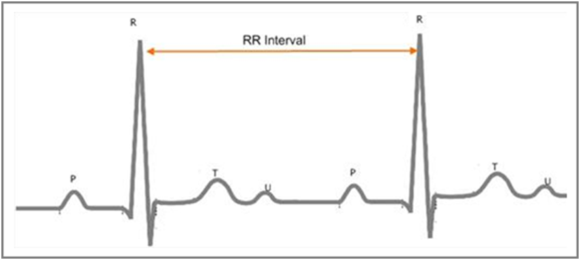
Figure 1. R Peaks and RR Intervals of an ECG Signal
The wave with the highest amplitude is the R wave. An RR interval is the time elapsed between two successive R waves. The waves with the lower amplitudes are the P wave, the T wave, and the U wave.
RR intervals show the variation between consecutive heartbeats. Heart rate variability (HRV) measurements analyze how these RR intervals change over time. Figure 2 shows the HRV of a typical adult.

Figure 2. HRV of an Adult
The data in Figure 2 shows that the RR intervals vary from 0.6 seconds to 1 second, with an average of 0.8 seconds.
HRV analysis provides a quantitative marker of the autonomic nervous system (ANS), because the regulation mechanisms of HRV originate from the sympathetic and parasympathetic nervous systems [5]. Researchers and engineers have published over 2,000 articles about HRV in the last ten years [1]. These articles observe the relationships between HRV and blood pressure, myocardial infarction, the nervous system, cardiac arrhythmia, and so on [2]. Various medical disciplines also have been researching HRV. HRV analysis will become more popular in graphical and data analysis for patients in the future.
To analyze heart rate variability (HRV), you first must acquire the RR intervals. Figure 3 shows the process of acquiring RR intervals.

Figure 3. RR Interval Acquisition Process
You can use various kinds of electrocardiographs to acquire electrocardiogram (ECG) signals. The bandwidths of these electrocardiographs are not very high. You can use National Instruments multichannel DAQ devices, such as the NI PCI-6221, to acquire raw ECG signals from the output terminals of ECG sensors. The sampling rates are typically 125 Hz or 250 Hz. You can store the acquired ECG signals in the NI TDMS file format for offline analysis. Online databases such as the MIT-BIH database also contain many typical ECG signals. The Biomedical Toolkit can import MIT-BIH ECG data directly using the palette VIs or the Biomedical Workbench.
You extract RR interval signals from raw ECG signals. The extraction process usually involves a preprocessing step and a peak detection step. It is necessary to preprocess the raw ECG signals if they have noise corruption and a significant baseline trend. You can then detect the R peaks by thresholding or using the wavelet-based peak detection method to compute the RR intervals.
There are different methods of heart rate variability (HRV) analysis [1] [2]. The time-domain analysis method extracts a few special measurements using only the temporal RR interval signals. The spectral analysis method interpolates the RR intervals at a certain rate and transforms these intervals into the frequency domain. There are some standards for these two methods [1]. Engineers have also discussed and researched other methods, such as nonlinear analysis and time-frequency analysis.
Figure 4 shows the entire process of HRV analysis.
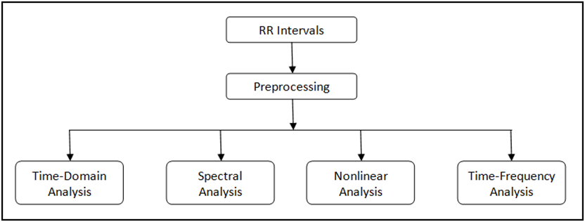
Figure 4. HRV Analysis Process
The Biomedical Toolkit provides a palette with several HRV analysis methods. You can select this palette through Biomedical»Biosignal Measurements»ECG»HRV Analysis. Figure 5 shows the HRV Analysis palette.

Figure 5. HRV Analysis Palette
The Biomedical Toolkit also contains a Heart Rate Variability Analyzer application for convenient HRV analysis. Figure 6 shows the Heart Rate Variability Analyzer application.
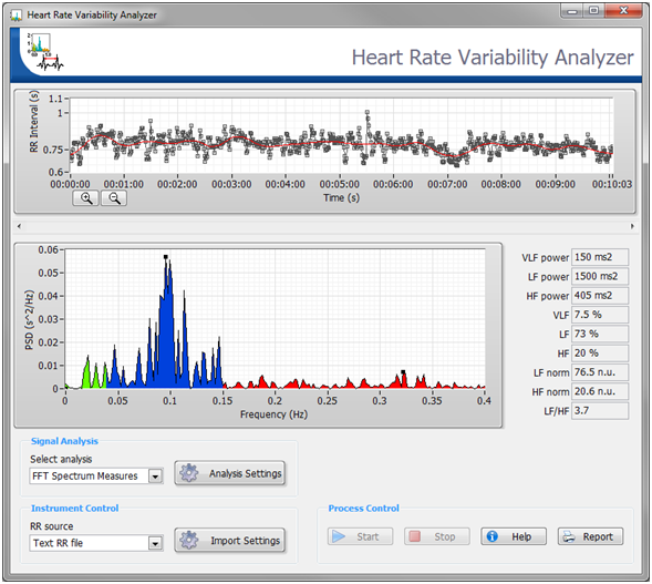
Figure 6. The Heart Rate Variability Analyzer in the Biomedical Workbench
RR interval signals sometimes show some baseline wandering, which results in inaccurate temporal and frequency analysis. You can choose whether to detrend the RR interval signals before analyzing them.
Figure 7 shows the detrending process for RR interval signals. The red line denotes the trend.

Figure 7. Detrending Process for RR Interval Signals
The following sections describe the different methods you can use to analyze RR interval signals.
For time series analysis, time-domain measurements are commonly used. You can extract many measurements from the original RR interval signals to show changes in the autonomic nervous system (ANS). The Biomedical Toolkit contains the HRV Statistics VI and the HRV Histogram VI. You can use these two VIs to extract several commonly used measurements, as shown in Table 1.
Table 1. Time-Domain Measurements of Heart Rate Variability [1] [5]
Variable | Unit | Description |
Statistical Measurements | ||
| RR Mean & Std | s | Mean and standard deviation of all RR intervals. |
| HR Mean & Std | 1/min | Mean and standard deviation of all heart rates. |
| RMSSD | ms | Square root of the mean of the sum of squares of differences between adjacent RR intervals. |
| NN50 Count | N/A | Number of pairs of adjacent RR intervals differing by more than 50 ms in all the measurements. |
| pNN50 | % | NN50 count divided by the total number of all RR intervals. |
Geometric Measurements | ||
| HRV Triangular Index | N/A | Total number of all RR intervals divided by the height of the histogram of all RR intervals. |
| TINN | ms | Baseline width of the minimum square difference triangular interpolation of the highest peak of the histogram of all RR intervals measured on a discrete scale with bins of 7·8125 ms (1/128 s). |
You can also use Heart Rate Variability Analyzer application to acquire these measurements. Figure 8 shows the analysis results of the signal shown in Figure 7.
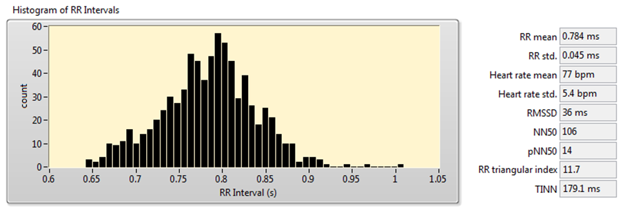
Figure 8. HRV Analysis Using the Time-Domain Analysis Method
The frequency-domain method of HRV analysis extracts frequency-domain parameters, such as peak frequency and power in band, from the RR interval signals. The two components of the autonomic nervous system (ANS), sympathetic and parasympathetic, increase or decrease the heart rate and influence different bands in the spectrum of RR intervals. Therefore, you can use frequency-domain analysis to monitor the state of the ANS.
Table 2 shows the common frequency-domain measurements of HRV analysis, including peak frequency and power in the very low-frequency (VLF), low-frequency (LF), and high-frequency (HF) bands.
Table 2. Frequency-Domain Measurements of HRV [1] [5]
Variable | Unit | Description |
| Peak Frequency | Hz | Peak frequencies of the power spectral density (PSD) estimate for the VLF, LF, and HF frequency bands. |
| VLF | ms2 | Power from 0 Hz to 0.04 Hz. |
| LF | ms2 | Power from 0.04 Hz to 0.15 Hz. |
| HF | ms2 | Power from 0.15 Hz to 0.40 Hz. |
| LF Norm | n.u. | LF power in normalized units: LF/(Total Power-VLF)*100. |
| HF Norm | n.u. | HF power in normalized units: HF/(Total Power-VLF)*100. |
| LF/HF Ratio | N/A | LF[ms2]/HF[ms2]. |
The Biomedical Toolkit provides the HRV FFT Spectrum VI and the HRV AR Spectrum VI for frequency-domain analysis. Using both of these VIs consists of the following three steps:
You usually do not use regular intervals to sample RR interval signals extracted from the ECG signals. Therefore, the RR interval signals along the time axis are not equally spaced, and you need to resample the raw RR intervals first. The HRV FFT Spectrum VI and the HRV AR Spectrum VI also accept signals that are already resampled. In this case, select either of the Even Sampled RR instances.
For PSD estimation, the HRV FFT Spectrum VI uses fast Fourier transform-based PSD, and the HRV AR Spectrum VI uses an autoregressive (AR) spectrum. The LabVIEW Advanced Signal Processing Toolkit, which is now included in LabVIEW Professional, also includes several other spectrum methods.
Figure 9 shows the results of frequency-domain analysis using the signal shown in Figure 7.
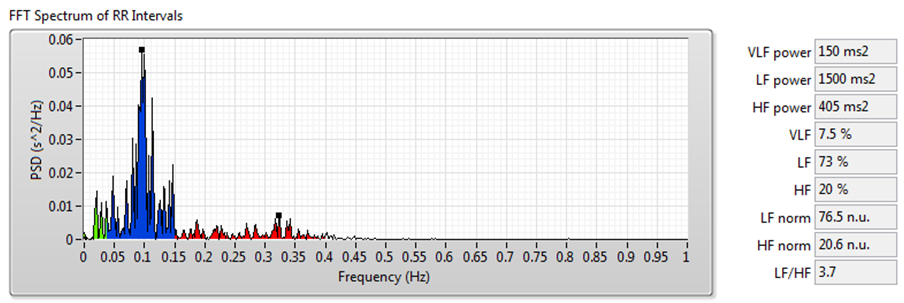

Figure 9. HRV Analysis Using the Frequency-Domain Analysis Method
The frequency-domain analysis method works well for RR interval signals that do not vary much over time. However, for such long-term HRV analyses as 24-hour RR intervals and drug pharmacodynamics research, RR interval signals vary significantly over time. In these situations, you can use joint time-frequency analysis (JTFA) to analyze stationarity and time-frequency behavior.
There are no standard measurements for the joint time-frequency-domain method. You can use short time Fourier transform (STFT), the Gabor expansion, or the continuous wavelet transform to show the time-frequency plots and perform qualitative analysis.
The Biomedical Toolkit now supports STFT. The Advanced Signal Processing Toolkit contains other methods. The Heart Rate Variability Analyzer application supports STFT, Gabor expansion, and continuous wavelet transform analysis.
Figure 10 shows the results of JTFA using the signal shown in Figure 7.


Figure 10. HRV Analysis Using the JTFA Method
The RR interval signals are nonlinear because they result from complex interactions of hemodynamics, electrophysiological, and humoral variables, as well as autonomic and central nervous regulations [1]. Very few studies have researched nonlinear analysis, so there are no standards. However, this is a promising area of research for discovering tools that can help to better the understanding of the complexity of the human system.
In the Biomedical Toolkit, the HRV Poincaré Plot VI supports the analysis of Poincaré plots. Furthermore, the Heart Rate Variability Analyzer also supports detrended fluctuation analysis (DFA) and recurrence map analysis.
A Poincaré plot is an XY graph whose x and y values are two consecutive RR intervals, respectively. The graph is modeled as an ellipse that is fitted on the line of symmetry at an angle 45° to the x-axis, as shown in Figure 11.
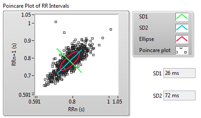
Figure 11. Poincaré Plot of RR Intervals
Figure 11 shows the following values:
The DFA method quantifies the fractal scaling properties of RR interval signals. This method minimizes erroneous correlation by removing non-stationary artificial trends. Therefore, the DFA method shows the changes of long-term HRV correlation better than other methods.
The DFA method uses linear fitting to analyze the DFA plot. The slope α of the fitted line indicates the long-range self correlation of HRV. If α = 0.5, the signals are white noise and have no correlation. In some situations, the DFA plot is not strictly linear but made up of two lines at a certain breakpoint. This situation suggests that there are two factors: a short-range scaling exponent over short periods and a long-range exponent over long periods [6].
Figure 12 shows the DFA result of the signal shown in Figure 7.
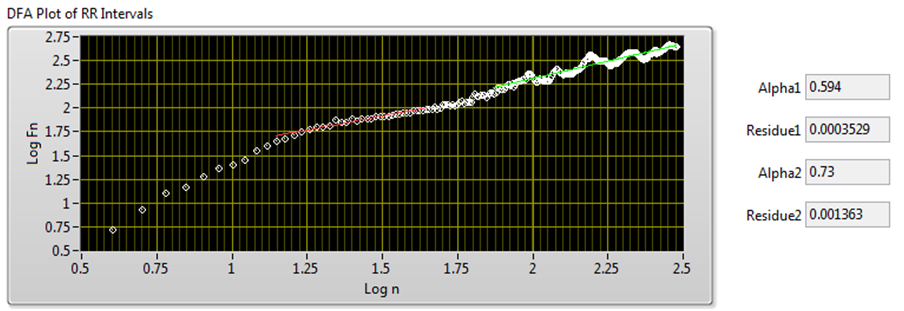
Figure 12. DFA Plot of RR Intervals
Clinical applications and research studies both apply heart rate variability analysis results. For statistical and frequency methods, some studies have presented standards for the use of HRV analysis to help diagnose various cardiac diseases in hospitals [1]. Using the Biomedical Toolkit (the VIs on the palette or the Heart Rate Variability Analyzer in Biomedical Workbench), researchers are able to find interesting relationships between HRV and diseases, as well as drug pharmacodynamics. For example, you may find some correlation between the ANS of a smoker versus that of a non-smoker. Different spectral measurements often show distinct differences in LF, HF, or LF/HF analysis, and researchers can use these differences to detect the influence of smoking on the ANS.
Note You can use Heart Rate Variability Analyzer in Biomedical Workbench for online HRV analysis.
You can download the evaluation version of the LabVIEW Biomedical Toolkit online. After installation, you can use the Heart Rate Variability Analyzer for free. You can use the palette VIs for a 45-day evaluation period.
[1] Task force of the European society of cardiology and the North American society of pacing and electrophysiology, Heart rate variability—standards of measurement, physiological interpretation, and clinical use, Circulation 1996(93),5, pp. 1043—1065.
[2] Rajendra Acharya U, Paul Joseph K, Kannathal N, Lim Choo Min and Jasjit Suri S, Heart Rate Variability, Advances in Cardiac Signal Processing, Springer-Verlag Berlin Heidelberg 2007,pp.121-165.
[3] U. Rajendra Acharya, N. Kannathal, Lim Choo Min and Jasjit S. Suri ,Linear, Non-Linear and Wavelet Analysis of Cardiac Health Using Heart Rate Signals, Advances in Cardiac Signal Processing, Springer-Verlag Berlin Heidelberg 2007,pp. 355-375.
[4] MICHAEL J. LEWIS, BSc, MSc, PhD, CPhys, MInstP, Heart Rate Variability Analysis: A Tool to Assess Cardiac Autonomic Function, CIN: Computers, Informatics, Nursing,2005(23),6,pp. 335-341.
[5] Juha-Pekka Niskanen, Mika P. Tarvainen, Perttu O. Ranta-aho, Pasi A. Karjalainen, Software for advanced HRV analysis, Computer Methods and Programs in Biomedicine,2004,76,pp.73-81
[6] Peng CK, Havlin S , Stanley HE , et al . Quantification of scaling exponents and crossover phenomena in nonstationary heartbeat time series. Chaos , 1995 , 5 (1),pp. 82-87.
[7] D. Singh, K. Vinod and S. C. Saxena, Sampling frequency of the RR interval time series for spectral analysis of heart rate variability, Journal of Medical Engineering & Technology, 2004(28), 6, pp. 263–272
[8] H G Adelmann, Heart Rate Variability Analysis in Clinical Pharmacology by Joint Time-Frequency Methods, Computers in Cardiology 1999, 26, pp. 643-645